
The Construction of My 1st Smithy
![]() Because my shop was
designed and built primarily for one specific purpose, that of being a
blacksmithing shop/decorative metal working studio, I decided to dedicate
a page to its construction. I should add that I do not plan to use this shop
as a typical "smithy" most of the time, but more of a metal arts studio where
I incorporate blacksmithing with other metal arts techniques. This is a narrative
of sorts, providing both a periodic progress update sequence and a discussion
of the various special features incorporated into the shop. I hope this page
will serve as a source for ideas that others may wish to consider when building
their own shops.
Because my shop was
designed and built primarily for one specific purpose, that of being a
blacksmithing shop/decorative metal working studio, I decided to dedicate
a page to its construction. I should add that I do not plan to use this shop
as a typical "smithy" most of the time, but more of a metal arts studio where
I incorporate blacksmithing with other metal arts techniques. This is a narrative
of sorts, providing both a periodic progress update sequence and a discussion
of the various special features incorporated into the shop. I hope this page
will serve as a source for ideas that others may wish to consider when building
their own shops.
![]() I should also explain
that the images and narrative are time transgressive. Images towards the
top of the page are superceeded by images later in the narrative. I did not
go back and update earlier parts of the narrative as I accomplished various
new tasks in the shop's construction sequence so as to preserve the full
sequence of the shop construction. So be aware that each image
you look at has probably been updated further down as new work was
completed.
I should also explain
that the images and narrative are time transgressive. Images towards the
top of the page are superceeded by images later in the narrative. I did not
go back and update earlier parts of the narrative as I accomplished various
new tasks in the shop's construction sequence so as to preserve the full
sequence of the shop construction. So be aware that each image
you look at has probably been updated further down as new work was
completed.
![]() I created a new page,
My Shop at a Glance, that will allow you to quickly
see the various features in my shop without reading through the detailed
text below. If you then wish to dig deeper into the various special features
in my shop, such as the induced draft hood and floor sockets, you may then
want to return to this page.
I created a new page,
My Shop at a Glance, that will allow you to quickly
see the various features in my shop without reading through the detailed
text below. If you then wish to dig deeper into the various special features
in my shop, such as the induced draft hood and floor sockets, you may then
want to return to this page.
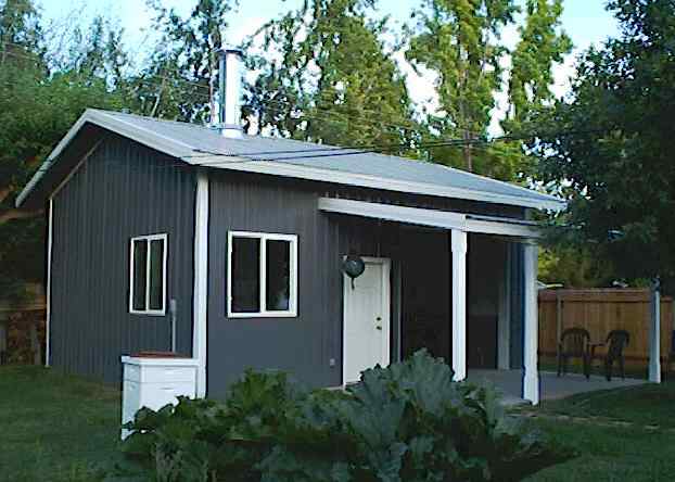
(Click picture for full sized image)
Shop on 6 Aug 01
First Real Snowfall of Winter 01/02
An Interesting Curl of Snow on the Roof
Jump to Updates
Power Hammer Installation
The Easy Hammer is Up and Running!
Shop's First Use
Foundry Bench Construction - The Last
Step
First Shop Demonstration
The New Anvil Arrives
Update Notes
![]() (19 Oct 01) Almost all of
the various parts of the shop mentioned below are now complete, including
the 3" wide by 1/8" steel kick strip around the base of the walls of the
shop. The only important thing that has not been completed at this writing
is the high "R" value compressed 8" batt ceiling insulation, which should
be installed sometime in the next two weeks....just in time for winter weather.
I have become somewhat distracted from work on the shop by "real" metal working
projects, such as a rattlesnake paper towel rack
for the shop, which I completed two days ago. I guess I got worn out with
construction projects, and needed to get my hands dirty working iron for
a change. The only two shop construction projects still waiting to be done
are the steel storage rack, and the foundry bench. The steel storage rack
will be done in the next month or so I suspect, but the bench will have to
wait until I get "a round tuit," and round tuits are hard to find.
(19 Oct 01) Almost all of
the various parts of the shop mentioned below are now complete, including
the 3" wide by 1/8" steel kick strip around the base of the walls of the
shop. The only important thing that has not been completed at this writing
is the high "R" value compressed 8" batt ceiling insulation, which should
be installed sometime in the next two weeks....just in time for winter weather.
I have become somewhat distracted from work on the shop by "real" metal working
projects, such as a rattlesnake paper towel rack
for the shop, which I completed two days ago. I guess I got worn out with
construction projects, and needed to get my hands dirty working iron for
a change. The only two shop construction projects still waiting to be done
are the steel storage rack, and the foundry bench. The steel storage rack
will be done in the next month or so I suspect, but the bench will have to
wait until I get "a round tuit," and round tuits are hard to find.
![]()
![]() (25 May 02) The only task
remaining at this time is to build the foundry bench. The ceiling insulation
is complete, as well as the 10' x 10' steel storage rack on the SW wall.
All the "to be built" items discussed below are now all complete and part
of the shop. The shop is a working smithy/metalworking studio now, complete
with plumbed in double regulated propane, and CO/CO2 detectors and alarms.
I finally found a "round tuit."
(25 May 02) The only task
remaining at this time is to build the foundry bench. The ceiling insulation
is complete, as well as the 10' x 10' steel storage rack on the SW wall.
All the "to be built" items discussed below are now all complete and part
of the shop. The shop is a working smithy/metalworking studio now, complete
with plumbed in double regulated propane, and CO/CO2 detectors and alarms.
I finally found a "round tuit."
![]() (6 Aug 02) The
foundry bench is complete now also, see bottom of page for
details. This completes the original list of
major shop construction items I made almost two years ago. It is hard to
believe that so much time, labor, and money, have been expended to get to
this point in time. I still have many small things that I will do, shelves,
hammer rack, exhaust fan, etc., but all of the big items are now complete.
What is even better is that I now feel free to return to building new equipment;
foundry sand muller, air and foot powered treadle hammer, clamshell forge,
foundry melting furnace, heat treating oven, etc. Truly, this marks the end
of the shop construction, and the beginning of a whole new phase of my life,
and my metalworking. There are so many possibilities...where to begin!
(6 Aug 02) The
foundry bench is complete now also, see bottom of page for
details. This completes the original list of
major shop construction items I made almost two years ago. It is hard to
believe that so much time, labor, and money, have been expended to get to
this point in time. I still have many small things that I will do, shelves,
hammer rack, exhaust fan, etc., but all of the big items are now complete.
What is even better is that I now feel free to return to building new equipment;
foundry sand muller, air and foot powered treadle hammer, clamshell forge,
foundry melting furnace, heat treating oven, etc. Truly, this marks the end
of the shop construction, and the beginning of a whole new phase of my life,
and my metalworking. There are so many possibilities...where to begin!
![]()
The Beginning
![]() Finally the day has
come that I now have my own long awaited "dream shop." Click the thumbnail
image above for a full size image of the finished building. It is not actually
finished in this image. The interior still has a lot of work left to be done.
However, the electrical is 90% complete, and the insulation about 30%. The
building was constructed with 2" blanket insulation throughout, but it will
have additional insulation on top of that, and then it will be covered with
chip-board and painted. I still have to mount the 4' x 5' steel exhaust hood
for the forges, and install and tie in the 12" diameter stainless tri-wall
chimney pipe. It will penetrate the roof in the corner of the building nearest
the camera.
Finally the day has
come that I now have my own long awaited "dream shop." Click the thumbnail
image above for a full size image of the finished building. It is not actually
finished in this image. The interior still has a lot of work left to be done.
However, the electrical is 90% complete, and the insulation about 30%. The
building was constructed with 2" blanket insulation throughout, but it will
have additional insulation on top of that, and then it will be covered with
chip-board and painted. I still have to mount the 4' x 5' steel exhaust hood
for the forges, and install and tie in the 12" diameter stainless tri-wall
chimney pipe. It will penetrate the roof in the corner of the building nearest
the camera.
![]() This building was designed
from the top down to be a blacksmith shop/metalworking studio. The concrete
floor slab varies in thickness from 6" in the "patio" slab, up to to 2' where
the power hammers will sit, and where the three 18" deep by 8" square floor
sockets are embedded. All concrete is 4000 psi fiber and rebar reinforced.
The outside covered "patio" slab is 10' by 18', and connected to the interior
by a 10' by 10' insulated industrial garage door, which makes it convenient
to work both inside and outside, and to aid in cooling in the summer. The
interior has a back, upper corner mounted, thermostatically controlled, 5
KW heating unit that blows down across the shop to the opposite lower back
corner. Mounted in the middle of the back half of the center roof support
truss is an industrial variable speed ceiling fan to pull the excess forging
heat down from the ceiling in the winter to circulate it throughout the shop
evenly, as well as to circulate the heat from the heating unit in a likewise
manor. This will save on heating costs in the winter. I want the shop to
be comfortably warm at all times in the winter, both for my comfort, and
to prevent sweating and rusting of my tools. The big ceiling fan also helps
in the summer when it becomes too hot.
This building was designed
from the top down to be a blacksmith shop/metalworking studio. The concrete
floor slab varies in thickness from 6" in the "patio" slab, up to to 2' where
the power hammers will sit, and where the three 18" deep by 8" square floor
sockets are embedded. All concrete is 4000 psi fiber and rebar reinforced.
The outside covered "patio" slab is 10' by 18', and connected to the interior
by a 10' by 10' insulated industrial garage door, which makes it convenient
to work both inside and outside, and to aid in cooling in the summer. The
interior has a back, upper corner mounted, thermostatically controlled, 5
KW heating unit that blows down across the shop to the opposite lower back
corner. Mounted in the middle of the back half of the center roof support
truss is an industrial variable speed ceiling fan to pull the excess forging
heat down from the ceiling in the winter to circulate it throughout the shop
evenly, as well as to circulate the heat from the heating unit in a likewise
manor. This will save on heating costs in the winter. I want the shop to
be comfortably warm at all times in the winter, both for my comfort, and
to prevent sweating and rusting of my tools. The big ceiling fan also helps
in the summer when it becomes too hot.
![]() You can't see it in
the picture, but there is an additional thermo-pane window in the back corner
to help ventilate the building. All windows are 4' x 4' thermopane. The building
is a "pole building," and is built on 8" square treated posts set 3' in the
ground, and bedded in concrete. The total floor area is a small 500 SF (20'
x 25'), because of P&Z set-back requirements. The additional "patio"
slab was put in to help offset the loss of interior floor area that I had
originally planned to have. It is very useful when doing grinding to keep
the grinding dust out of the shop.
You can't see it in
the picture, but there is an additional thermo-pane window in the back corner
to help ventilate the building. All windows are 4' x 4' thermopane. The building
is a "pole building," and is built on 8" square treated posts set 3' in the
ground, and bedded in concrete. The total floor area is a small 500 SF (20'
x 25'), because of P&Z set-back requirements. The additional "patio"
slab was put in to help offset the loss of interior floor area that I had
originally planned to have. It is very useful when doing grinding to keep
the grinding dust out of the shop.
![]() Although I have not
put them in yet, there will be continuous strip mounted 110V power outlets
along all sides of the shop, and also 220V outlets where needed to service
the welders, power hammer(s), compressor, and plasma cutter. I am waiting
on these until I complete the insulation and walls. Presently there is a
temporary bank of 110 and 220 volt outlets in the corner under the electrical
box. Also, the shop may have a compressed air line with a number of quick
disconnects routed around the perimeter of the shop. Along side the air line
will be a propane line, also with four quick disconnects, where the forges
will be used, and where hot work will be done on counter or table tops. The
propane bottles will be outside in back where the first regulator is located
to set the upper end pressure of 15 psi for the interior supply line. There
will be a shut off valve inside the building where the pipe line enters
to isolate the building from the pressure tanks after I am done forging,
and another regulator at the forge to adjust for operating pressure
needs.
Although I have not
put them in yet, there will be continuous strip mounted 110V power outlets
along all sides of the shop, and also 220V outlets where needed to service
the welders, power hammer(s), compressor, and plasma cutter. I am waiting
on these until I complete the insulation and walls. Presently there is a
temporary bank of 110 and 220 volt outlets in the corner under the electrical
box. Also, the shop may have a compressed air line with a number of quick
disconnects routed around the perimeter of the shop. Along side the air line
will be a propane line, also with four quick disconnects, where the forges
will be used, and where hot work will be done on counter or table tops. The
propane bottles will be outside in back where the first regulator is located
to set the upper end pressure of 15 psi for the interior supply line. There
will be a shut off valve inside the building where the pipe line enters
to isolate the building from the pressure tanks after I am done forging,
and another regulator at the forge to adjust for operating pressure
needs.
![]() I was vary fortunate
because my house electrical service had enough spare capacity that I was
able to have a line brought over to the near corner of the shop by trench
from my existing electrical service to service the shop with 100 amp 220V
capacity, thus saving the cost of a new service and its associated monthly
billing expense.
I was vary fortunate
because my house electrical service had enough spare capacity that I was
able to have a line brought over to the near corner of the shop by trench
from my existing electrical service to service the shop with 100 amp 220V
capacity, thus saving the cost of a new service and its associated monthly
billing expense.
![]() One of the floor sockets
will have an 8" square timber post mounted in it to provide a mounting post
for my 6" and 8" post vises, which will be mounted opposite to each other.
I have three other post vises that will be mounted on various benches. You
can't have too many post vises. The second floor socket will have
another 8" wood post to mount my two post drills, one big and one small,
also on opposite sides of the post. The third floor socket is a spare for
whatever comes along. I fabricated the floor sockets out of 3/8" wall x 8"
square steel tubing sections, 18" long. They have a steel plate welded across
the bottom, and concrete bonding steel welded on the outside to provide a
solid bond to the concrete. "Moose Milk" was applied to all surfaces prior
to embedment to provide a rock solid bond to the concrete. When
the floor slab was placed we put in 2' square block-outs where each socket
would go. This made it easy to precisely align and position the floor socket
"cans" prior to embedment, which was done at a later date. I wanted them
to be as plumb as possible, and by drilling and placing rebar studs in the
walls of the block-out openings we were able to lock them firmly in place.
There was no movement when the concrete was vibrated into each deep socket
hole. I highly recommend this method, even though you end up with a contact
line between the two pours.
One of the floor sockets
will have an 8" square timber post mounted in it to provide a mounting post
for my 6" and 8" post vises, which will be mounted opposite to each other.
I have three other post vises that will be mounted on various benches. You
can't have too many post vises. The second floor socket will have
another 8" wood post to mount my two post drills, one big and one small,
also on opposite sides of the post. The third floor socket is a spare for
whatever comes along. I fabricated the floor sockets out of 3/8" wall x 8"
square steel tubing sections, 18" long. They have a steel plate welded across
the bottom, and concrete bonding steel welded on the outside to provide a
solid bond to the concrete. "Moose Milk" was applied to all surfaces prior
to embedment to provide a rock solid bond to the concrete. When
the floor slab was placed we put in 2' square block-outs where each socket
would go. This made it easy to precisely align and position the floor socket
"cans" prior to embedment, which was done at a later date. I wanted them
to be as plumb as possible, and by drilling and placing rebar studs in the
walls of the block-out openings we were able to lock them firmly in place.
There was no movement when the concrete was vibrated into each deep socket
hole. I highly recommend this method, even though you end up with a contact
line between the two pours.
![]() I thought long and hard
about the lighting. I opted to use incandescent lights due to their superior
light quality and true temper color appearance when working with metal, even
though they cost more to operate. The shop has four banks of five 150 watt
lights. Each bank is individually switched to allow me to use only what is
needed. I may replace the on/off switches with variable switches to vary
the lighting intensity as needed. I don't like other kinds of lighting due
to a variety of reasons, among them being they are hard on the eyes, don't
like to start in cold temperatures, and the light has a false color spectrum
which results in false temper colors.
I thought long and hard
about the lighting. I opted to use incandescent lights due to their superior
light quality and true temper color appearance when working with metal, even
though they cost more to operate. The shop has four banks of five 150 watt
lights. Each bank is individually switched to allow me to use only what is
needed. I may replace the on/off switches with variable switches to vary
the lighting intensity as needed. I don't like other kinds of lighting due
to a variety of reasons, among them being they are hard on the eyes, don't
like to start in cold temperatures, and the light has a false color spectrum
which results in false temper colors.
![]() Well, there is a lot
more to relate about the shop, but I need to give it up for tonight. I have
been putting in 12-14 hour days for weeks now, and it is beginning to have
its effect on me. Check back for updates as time permits, such as the jet
inductor in the chimney, and other features I am adding.
Well, there is a lot
more to relate about the shop, but I need to give it up for tonight. I have
been putting in 12-14 hour days for weeks now, and it is beginning to have
its effect on me. Check back for updates as time permits, such as the jet
inductor in the chimney, and other features I am adding.
![]() (25 June 01)
The shop is coming along very well. This image
shows the forced draft hood which I completed today. The draft
is created by the inducer blower, seen at the top right, and is connected
to the 12" diameter chimney by the black horizontal 2" diameter rubber flex
pipe. The heavy gage chimney pipe provides all the needed stability for the
hood so that no additional bracing is required. The hood is rock solid when
pushed or rotated. This was possible due to the heavy gage chimney pipe that
I used between the hood and the chimney box in the roof. The hood has a 3'
section of 12" diameter, 16 gage pipe which connects to the roof box through
a removable 17" length of 20 gage pipe. If I had used the much lighter commercial
weight (about 26 gage) stove pipe it would not have had the strength to transfer
the structural integrity provided by the roof box to the hood, and I would
have had to use additional hood bracing. Notice in the image the faint trace
of the cross breaks I had put in each face of the hood. This prevents the
hood from "booming" when the metal expands as it heats and cools. All the
metal is under tension, with no flex in any face. Flat faces can be noisy.
Also, the cross breaks provide a visually pleasing raised pattern on each
face. The hood is fabricated out of 16 gage steel, and putting the breaks
in, and getting everything to line up for welding caused some fabrication
challenges, but worked out very well in the end.
(25 June 01)
The shop is coming along very well. This image
shows the forced draft hood which I completed today. The draft
is created by the inducer blower, seen at the top right, and is connected
to the 12" diameter chimney by the black horizontal 2" diameter rubber flex
pipe. The heavy gage chimney pipe provides all the needed stability for the
hood so that no additional bracing is required. The hood is rock solid when
pushed or rotated. This was possible due to the heavy gage chimney pipe that
I used between the hood and the chimney box in the roof. The hood has a 3'
section of 12" diameter, 16 gage pipe which connects to the roof box through
a removable 17" length of 20 gage pipe. If I had used the much lighter commercial
weight (about 26 gage) stove pipe it would not have had the strength to transfer
the structural integrity provided by the roof box to the hood, and I would
have had to use additional hood bracing. Notice in the image the faint trace
of the cross breaks I had put in each face of the hood. This prevents the
hood from "booming" when the metal expands as it heats and cools. All the
metal is under tension, with no flex in any face. Flat faces can be noisy.
Also, the cross breaks provide a visually pleasing raised pattern on each
face. The hood is fabricated out of 16 gage steel, and putting the breaks
in, and getting everything to line up for welding caused some fabrication
challenges, but worked out very well in the end.
![]() The hood is suspended
on 1/2" "all-thread." This allows the hood to be lowered for insertion of
the 17" length of stove pipe, and then raised into its final position. It
also made it easy to set the hood elevation to whatever I desired. In this
case its 1/2" above the top of my head. Also, the four upper nuts on the
all-thread made it easy to precisely level the hood. The vertical alignment
was controlled through use of a plumb-bob which hung at the center point
of the future roof penetration throughout the hood mounting process. It worked
well enough that the chimney lined up perfectly with the nipple on the roof
box, so that the chimney section between the roof box and hood is perfectly
plumb, at least within the limits of my levels. It was very gratifying when
I installed the 17" pipe section and everything lined up perfectly the first
time. Using care and careful measurement throughout the construction process
pays back big dividends in the end. An example I am proud of is the wooden
2x6 suspension frame for the hood. When it was finished I strung two diagonal
string lines between its corners, passing under the point of the reference
plumb-bob, and the string intersection point, and point of the plumb-bob,
matched within 1/32", and that precision carried over to the center-line
location of the hood's 3' chimney pipe. Everything is square, level, and
plumb.
The hood is suspended
on 1/2" "all-thread." This allows the hood to be lowered for insertion of
the 17" length of stove pipe, and then raised into its final position. It
also made it easy to set the hood elevation to whatever I desired. In this
case its 1/2" above the top of my head. Also, the four upper nuts on the
all-thread made it easy to precisely level the hood. The vertical alignment
was controlled through use of a plumb-bob which hung at the center point
of the future roof penetration throughout the hood mounting process. It worked
well enough that the chimney lined up perfectly with the nipple on the roof
box, so that the chimney section between the roof box and hood is perfectly
plumb, at least within the limits of my levels. It was very gratifying when
I installed the 17" pipe section and everything lined up perfectly the first
time. Using care and careful measurement throughout the construction process
pays back big dividends in the end. An example I am proud of is the wooden
2x6 suspension frame for the hood. When it was finished I strung two diagonal
string lines between its corners, passing under the point of the reference
plumb-bob, and the string intersection point, and point of the plumb-bob,
matched within 1/32", and that precision carried over to the center-line
location of the hood's 3' chimney pipe. Everything is square, level, and
plumb.
![]() You can see the forge
running in this image. Before I fired up the forge
I wanted to see if my inducer jet was creating the draft I wanted. I threw
a piece of crumpled up paper up into the hood while it was running, and the
paper was sucked up and blown out the top of the chimney. When the forge
is running the draft is strong enough that I can feel it on my legs. The
air being drawn up into the hood pulls the forge gasses directly up and away
so that there is no contact with them. This will be a very big benefit for
my lungs, to be sure. During the winter I will close the damper to balance
the input from the forge, but during the summer will keep the damper wide
open to use it for its ventilating ability.
You can see the forge
running in this image. Before I fired up the forge
I wanted to see if my inducer jet was creating the draft I wanted. I threw
a piece of crumpled up paper up into the hood while it was running, and the
paper was sucked up and blown out the top of the chimney. When the forge
is running the draft is strong enough that I can feel it on my legs. The
air being drawn up into the hood pulls the forge gasses directly up and away
so that there is no contact with them. This will be a very big benefit for
my lungs, to be sure. During the winter I will close the damper to balance
the input from the forge, but during the summer will keep the damper wide
open to use it for its ventilating ability.
![]() The wall board, and
wall insulation, are in place now, and only need to be prepped and painted.
I am going to install a 1/8" x 2" steel "kick strip" along the base of all
the walls to prevent hot-cut ends from sliding over to the walls and coming
in contact with something flammable. I rarely lose a hot-cut end, but it
does happen on occasion. I still need to install my 8" post vise on the white
post in the lower left of the image. I need to fabricate a steel cap to reinforce
the 8" square post first however. I also need to finish the electrical work
now that the wall board is in place. Each "bay" of the shop has separate
110 volt, 20 amp, and 220 volt, 20 amp, junction boxes to allow installation
of receptacles for each voltage in each bay. There is a separate 220 volt
50 amp circuit that will service all the heavy draw tools, such as welders,
compressor, and plasma cutter. I have a number of 6' long, 110 volt, receptacle
strips with receptacles every 6" that will be installed over each work bench
location.
The wall board, and
wall insulation, are in place now, and only need to be prepped and painted.
I am going to install a 1/8" x 2" steel "kick strip" along the base of all
the walls to prevent hot-cut ends from sliding over to the walls and coming
in contact with something flammable. I rarely lose a hot-cut end, but it
does happen on occasion. I still need to install my 8" post vise on the white
post in the lower left of the image. I need to fabricate a steel cap to reinforce
the 8" square post first however. I also need to finish the electrical work
now that the wall board is in place. Each "bay" of the shop has separate
110 volt, 20 amp, and 220 volt, 20 amp, junction boxes to allow installation
of receptacles for each voltage in each bay. There is a separate 220 volt
50 amp circuit that will service all the heavy draw tools, such as welders,
compressor, and plasma cutter. I have a number of 6' long, 110 volt, receptacle
strips with receptacles every 6" that will be installed over each work bench
location.
![]() As you can see, my "dream
shop" is coming along very well. I have been putting in very long days, up
to 17 hours a day, seven days a week, so it shouldn't be too much longer
before the shop is up and running. One beneficial side effect is that I have
lost 24 pounds so far due to the long days working in the shop. The chimney
was quite a piece of work. It is a 12" diameter "tri-wall rated," actually
double wall pipe, that I installed during three long, very hot, days. It
only sticks 5 feet above the roof, so by code, and by the chimney pipe company
instructions, I didn't need any guy wires. I had second thoughts after it
was done, and the next morning I installed guy wires, which took all play
out of the chimney that was caused by the twist lock joints in the pipe.
The next day we were hit by a very powerful wind and dust storm, with winds
of 45-60 mph. I was very glad to have the guy wires in place as the chimney
didn't move at all, even in the heaviest gusts. Today it has been raining
and there hasn't been any leakage, so apparently it has passed the test and
I have a sound installation.
As you can see, my "dream
shop" is coming along very well. I have been putting in very long days, up
to 17 hours a day, seven days a week, so it shouldn't be too much longer
before the shop is up and running. One beneficial side effect is that I have
lost 24 pounds so far due to the long days working in the shop. The chimney
was quite a piece of work. It is a 12" diameter "tri-wall rated," actually
double wall pipe, that I installed during three long, very hot, days. It
only sticks 5 feet above the roof, so by code, and by the chimney pipe company
instructions, I didn't need any guy wires. I had second thoughts after it
was done, and the next morning I installed guy wires, which took all play
out of the chimney that was caused by the twist lock joints in the pipe.
The next day we were hit by a very powerful wind and dust storm, with winds
of 45-60 mph. I was very glad to have the guy wires in place as the chimney
didn't move at all, even in the heaviest gusts. Today it has been raining
and there hasn't been any leakage, so apparently it has passed the test and
I have a sound installation.
![]() (30 June 01)
I achieved a dream that I have had for 5-6 years yesterday when I completed
the mounting of two of my post vises on one of the
8" floor socket posts. The vise on the right in the image is an
8" Colombian that I obtained 5 or 6 years ago after
driving 750 miles round trip to Walla Walla, Washington to a fellow's ranch
after he had told me he had a "big" post vise for sale. The vise turned out
to be a superb, almost new, Colombian vise, so I bought it and returned home
a tired but happy smith. The vise has been stored in my shed for all
of this time waiting for the day when I would have a shop to mount it in.
Yesterday that day finally arrived. The vise is so big that its mounting
plate can barely fit on the top of an 8" diameter post, so I made an 8 sided
steel cap for the post to reinforce it and prevent the 1/2" x 6" lag bolts
from splitting out the sides of the post. It does have 8 sides due to the
small flats that are in the corners to match where the post has 3/4" bevels
on its corners. I also welded on an additional mounting plate in order to
mount a 7" Colombian on the opposite side of the post. It has the copper
jaw covers on it in the image. I have two additional post vises that will
be installed in the shop on the work benches, a 5" and a 4" vise, all in
very good to excellent condition. I have been buying, reconditioning, and
selling vises for quite some time, and have kept the very best ones for my
shop. The 8" Colombian is the best of the best. To improve the utility of
the vise work stations I added a tray between the vises
to hold tools such as files, hammers, etc. This is a big help when working
at one of the vises.
(30 June 01)
I achieved a dream that I have had for 5-6 years yesterday when I completed
the mounting of two of my post vises on one of the
8" floor socket posts. The vise on the right in the image is an
8" Colombian that I obtained 5 or 6 years ago after
driving 750 miles round trip to Walla Walla, Washington to a fellow's ranch
after he had told me he had a "big" post vise for sale. The vise turned out
to be a superb, almost new, Colombian vise, so I bought it and returned home
a tired but happy smith. The vise has been stored in my shed for all
of this time waiting for the day when I would have a shop to mount it in.
Yesterday that day finally arrived. The vise is so big that its mounting
plate can barely fit on the top of an 8" diameter post, so I made an 8 sided
steel cap for the post to reinforce it and prevent the 1/2" x 6" lag bolts
from splitting out the sides of the post. It does have 8 sides due to the
small flats that are in the corners to match where the post has 3/4" bevels
on its corners. I also welded on an additional mounting plate in order to
mount a 7" Colombian on the opposite side of the post. It has the copper
jaw covers on it in the image. I have two additional post vises that will
be installed in the shop on the work benches, a 5" and a 4" vise, all in
very good to excellent condition. I have been buying, reconditioning, and
selling vises for quite some time, and have kept the very best ones for my
shop. The 8" Colombian is the best of the best. To improve the utility of
the vise work stations I added a tray between the vises
to hold tools such as files, hammers, etc. This is a big help when working
at one of the vises.
![]() (9 July 01) Although
it has been really hot and humid lately, the shop is still coming along
on schedule. I completed the painting of the first 1/3
of the shop today. This was by far the hardest part of the paint job,
due to the garage door, walk door, two windows, hood support structure, and
various other things that make painting tedious. I also installed the molding
around the door and windows, closing them in and giving them a finished
look. I am very pleased with how it is coming out, but displeased with
the Glidden paint I am using. The white paint is easily seen through with
just one coat, and even with a white primer underneath it. If I didn't already
have all the paint needed to complete the shop I would switch to a different
higher quality brand. The gray paint performs fine, and it is Glidden also,
so apparently its just the white paint that has problems.
(9 July 01) Although
it has been really hot and humid lately, the shop is still coming along
on schedule. I completed the painting of the first 1/3
of the shop today. This was by far the hardest part of the paint job,
due to the garage door, walk door, two windows, hood support structure, and
various other things that make painting tedious. I also installed the molding
around the door and windows, closing them in and giving them a finished
look. I am very pleased with how it is coming out, but displeased with
the Glidden paint I am using. The white paint is easily seen through with
just one coat, and even with a white primer underneath it. If I didn't already
have all the paint needed to complete the shop I would switch to a different
higher quality brand. The gray paint performs fine, and it is Glidden also,
so apparently its just the white paint that has problems.
![]() When I was picking up
the molding and lumber to finish the windows and door, I also picked up the
steel to make the "kick strips" for the base of the walls. I ended up getting
1/8" x 3" steel instead of the 2" wide steel I had planned on. Not because
I changed my mind, but because the steel yard was out of the 2" stock. I
am now pleased that I am using 3" as it will look much better, even if it
will have no additional practical value in preventing fires when hot cut
pieces of steel take off for parts unknown. I will spray it with
flat black BBQ paint prior to installing it.
When I was picking up
the molding and lumber to finish the windows and door, I also picked up the
steel to make the "kick strips" for the base of the walls. I ended up getting
1/8" x 3" steel instead of the 2" wide steel I had planned on. Not because
I changed my mind, but because the steel yard was out of the 2" stock. I
am now pleased that I am using 3" as it will look much better, even if it
will have no additional practical value in preventing fires when hot cut
pieces of steel take off for parts unknown. I will spray it with
flat black BBQ paint prior to installing it.
![]() BTW, in the above image,
a structure can be seen above the door that may be a source of curiosity.
It was just an opening left after the framing to support the awning structure
outside was completed, and instead of simply filling it with insulation and
closing it in, I decided to make a decorative inset shelf out of it to place
some of my ironwork and gifts for display. It would have been easier to just
cover it up, but I think it will add something to the shop, so I insulated
it with bead-board and finished it with the same chip-board that the walls
of the shop are done with. The bottom board sticks out 3" beyond the wall
face providing a nice 8" deep area for a few pieces of metalwork. A shop
doesn't need to be a barren sterile place to work.
BTW, in the above image,
a structure can be seen above the door that may be a source of curiosity.
It was just an opening left after the framing to support the awning structure
outside was completed, and instead of simply filling it with insulation and
closing it in, I decided to make a decorative inset shelf out of it to place
some of my ironwork and gifts for display. It would have been easier to just
cover it up, but I think it will add something to the shop, so I insulated
it with bead-board and finished it with the same chip-board that the walls
of the shop are done with. The bottom board sticks out 3" beyond the wall
face providing a nice 8" deep area for a few pieces of metalwork. A shop
doesn't need to be a barren sterile place to work.
![]() The gray color I am
using in the shop was suggest by Nahum Hersom a couple weeks ago during one
of his many visits to my shop. I had planned to use nothing but white paint.
I am now very glad that he made the suggestion, because it not only looks
a lot better, but has the practical value that it will not show the dirt
as much, and is a high gloss paint so it is more easily cleaned than the
semi-gloss white paint above it. As you can see in the image, the white paint
really makes a huge difference in the light level in the shop, as compared
with the previous images posted here. With only two of the overhead light
banks on it was almost too bright for the camera, where before, I was unable
to get enough light in my images with all four banks of lights on. It should
be quite impressive when the whole shop has been painted. I may have to wear
my welding hood in the shop to cut the light level....grin. I plan to put
one bank of lights on a dimmer switch so that I can cut the light level to
a minimum while forging to more easily see the temperature color of the metal.
The other three banks of lights will be switched off during forging. Just
for information, I have a total of 3000 watts of incandescent lighting, made
up of four banks of five 150 watt bulbs, in order to be able to get the needed
light levels for any kind of work I may be engaged in. This lighting was
"engineered" to deliver the proper lumens from their 12-15 foot distance
above the floor. At first I thought it would be excessive, but not now after
having used them when the shop was white inside due to the exposed insulation.
Normally I will use no more than two banks at any one time.
The gray color I am
using in the shop was suggest by Nahum Hersom a couple weeks ago during one
of his many visits to my shop. I had planned to use nothing but white paint.
I am now very glad that he made the suggestion, because it not only looks
a lot better, but has the practical value that it will not show the dirt
as much, and is a high gloss paint so it is more easily cleaned than the
semi-gloss white paint above it. As you can see in the image, the white paint
really makes a huge difference in the light level in the shop, as compared
with the previous images posted here. With only two of the overhead light
banks on it was almost too bright for the camera, where before, I was unable
to get enough light in my images with all four banks of lights on. It should
be quite impressive when the whole shop has been painted. I may have to wear
my welding hood in the shop to cut the light level....grin. I plan to put
one bank of lights on a dimmer switch so that I can cut the light level to
a minimum while forging to more easily see the temperature color of the metal.
The other three banks of lights will be switched off during forging. Just
for information, I have a total of 3000 watts of incandescent lighting, made
up of four banks of five 150 watt bulbs, in order to be able to get the needed
light levels for any kind of work I may be engaged in. This lighting was
"engineered" to deliver the proper lumens from their 12-15 foot distance
above the floor. At first I thought it would be excessive, but not now after
having used them when the shop was white inside due to the exposed insulation.
Normally I will use no more than two banks at any one time.
![]() (29 July
01) A lot has been accomplished on the shop since my last
entry. The painting is now complete! That was one of the most difficult jobs
of the entire project of building this structure, or at least the one I most
disliked doing. I finally determined that I could get a good result with
the Glidden paint if I used a roller and applied two coats of the white top-coat.
I went back and rolled all the areas I had painted with a brush, and they
now look smooth and uniform. The gray lower paint was really a wonderful
idea as it cuts the starkness of the bright white paint, and provides a pleasing
effect overall. I have Nahum Hersom to thank for that. He has offered many
suggestions during his numerous visits to my "shop in progress," and most
of them I have incorporated into its design.
(29 July
01) A lot has been accomplished on the shop since my last
entry. The painting is now complete! That was one of the most difficult jobs
of the entire project of building this structure, or at least the one I most
disliked doing. I finally determined that I could get a good result with
the Glidden paint if I used a roller and applied two coats of the white top-coat.
I went back and rolled all the areas I had painted with a brush, and they
now look smooth and uniform. The gray lower paint was really a wonderful
idea as it cuts the starkness of the bright white paint, and provides a pleasing
effect overall. I have Nahum Hersom to thank for that. He has offered many
suggestions during his numerous visits to my "shop in progress," and most
of them I have incorporated into its design.
![]() Following the completion
of the painting I didn't sit around long enjoying the shop before I started
in on the next important step, that of building the propane
shed (second image with door closed) and getting
it plumbed into the shop. I don't like having propane bottles in a building,
and especially not around an operating forge. My goal was to build a well
designed and constructed propane bottle storage shed, where a regulator on
the bottle in use would step the pressure down to 15 psi before it entered
the shop's interior propane distribution pipe line. There would be a second
regulator at the point of use. I am happy to report that this system is now
complete, except for a latch on the propane shed door, which I will forge
today after completing this update. The exterior dimensions of the
shed, before sheathing, are 4' x 4' x 2', and it can hold three of the
medium sized bottles of propane and one smaller one. The medium sized
bottles, about 12 gallons, are as big as I wish to lift to haul to the filling
station.
Following the completion
of the painting I didn't sit around long enjoying the shop before I started
in on the next important step, that of building the propane
shed (second image with door closed) and getting
it plumbed into the shop. I don't like having propane bottles in a building,
and especially not around an operating forge. My goal was to build a well
designed and constructed propane bottle storage shed, where a regulator on
the bottle in use would step the pressure down to 15 psi before it entered
the shop's interior propane distribution pipe line. There would be a second
regulator at the point of use. I am happy to report that this system is now
complete, except for a latch on the propane shed door, which I will forge
today after completing this update. The exterior dimensions of the
shed, before sheathing, are 4' x 4' x 2', and it can hold three of the
medium sized bottles of propane and one smaller one. The medium sized
bottles, about 12 gallons, are as big as I wish to lift to haul to the filling
station.
![]() The storage structure
and distribution system are now a reality, and a very successful one. The
propane shed, shown in the image linked above, was constructed almost entirely
out of materials left over from the construction of my shop building. The
only "new" materials are the four treated 4x4 support posts that are set
into the ground 3', to get below the frost line, and concreted in place.
The shed is very heavily built, as is my practice when I build things for
myself. The basic frame structure is constructed from 2x4 and 2x6 lumber,
with OSB chip-board on top. I used the leftover steel sheathing and trim
from the shop to cover the exterior. I was very fortunate that there was
enough of everything to finish the job.
The storage structure
and distribution system are now a reality, and a very successful one. The
propane shed, shown in the image linked above, was constructed almost entirely
out of materials left over from the construction of my shop building. The
only "new" materials are the four treated 4x4 support posts that are set
into the ground 3', to get below the frost line, and concreted in place.
The shed is very heavily built, as is my practice when I build things for
myself. The basic frame structure is constructed from 2x4 and 2x6 lumber,
with OSB chip-board on top. I used the leftover steel sheathing and trim
from the shop to cover the exterior. I was very fortunate that there was
enough of everything to finish the job.
![]() The only difficult
part was the cutting to size of the sheet metal. I have various aircraft
sheet metal shears, and they proved to be very valuable for cutting the
corrugations of the sheathing. The only down side is that it made my hands
VERY sore after a full day of cutting steel sheet and trim. I do not like
working with sheet metal, so was very happy to see the end of this phase
of the work.
The only difficult
part was the cutting to size of the sheet metal. I have various aircraft
sheet metal shears, and they proved to be very valuable for cutting the
corrugations of the sheathing. The only down side is that it made my hands
VERY sore after a full day of cutting steel sheet and trim. I do not like
working with sheet metal, so was very happy to see the end of this phase
of the work.
![]() The shed has a 3/8",
heavy wall, brass pipe line that enters it from the under side. I installed
the pipe very close to the shop building, prior to the shed being built,
so that the shed needed to be very close also in order to allow the pipe
to enter through the floor and come up the inside face of the back wall of
the shed. The pipe enters the ground from the shed and travels up inside
one of the corrugations in the shop wall, and then makes a 90 degree turn
and penetrates into the shop interior where it has its first ball valve.
I didn't want to put any holes into the siding of the shop, and this system
worked very well.
The shed has a 3/8",
heavy wall, brass pipe line that enters it from the under side. I installed
the pipe very close to the shop building, prior to the shed being built,
so that the shed needed to be very close also in order to allow the pipe
to enter through the floor and come up the inside face of the back wall of
the shed. The pipe enters the ground from the shed and travels up inside
one of the corrugations in the shop wall, and then makes a 90 degree turn
and penetrates into the shop interior where it has its first ball valve.
I didn't want to put any holes into the siding of the shop, and this system
worked very well.
![]() Once the propane storage
shed was built, I found that it got excessively hot inside during the three
hours of exposure it gets to the sun each mid-day. I have two sets of 1"
diameter ventilation holes in the shed, one set in the upper back wall,
and one set in the perimeter of the floor to drain away any leaking propane,
but they were not enough to keep it cool inside. I had a lot of left over
1" insulation board, so installed a full lining of insulation in the interior
of the shed, except for the back wall, which isn't exposed to the sun. The
insulation can be seen behind the propane bottle on the right in the image.
That took care of the heating problems. It now remains relatively cool inside,
even when the temperature outside reaches over 100 degrees, as we have been
experiencing lately.
Once the propane storage
shed was built, I found that it got excessively hot inside during the three
hours of exposure it gets to the sun each mid-day. I have two sets of 1"
diameter ventilation holes in the shed, one set in the upper back wall,
and one set in the perimeter of the floor to drain away any leaking propane,
but they were not enough to keep it cool inside. I had a lot of left over
1" insulation board, so installed a full lining of insulation in the interior
of the shed, except for the back wall, which isn't exposed to the sun. The
insulation can be seen behind the propane bottle on the right in the image.
That took care of the heating problems. It now remains relatively cool inside,
even when the temperature outside reaches over 100 degrees, as we have been
experiencing lately.
![]() You may have noticed
the white shed door in the image. I was going to sheath the door with the
same steel sheathing used on the rest of the shed, but decided that it would
look better if it were painted white instead. The door is very heavily
constructed out of ripped 2x6 lumber and OSB chip-board. There are no butted
joints in the door. All the lumber was cut with 45 degree miter angles on
the ends for proper framing of the door. It was then glued and screwed to
the OSB board to make a rock solid and heavy door. I don't have problems
with uninvited guests entering my yard, but it will be good to have the security
the heavy construction offers, once I have the latch forged and installed.
BTW, the angle of the image makes the door look out of alignment...it isn't.
Everything is plumb and square within a 32nd of an inch. The hinges on the
door are solid brass. I took my magnet to the store when I went to get them
to be sure that they were indeed solid brass. I found that the packages labelled
"brass hinge" are in fact steel with brass plating. The packages labelled
"solid brass" are truly solid brass. I wanted solid brass because the door
will only be used occasionally, and the location of the shed is prone to
dampness in the winter, so the hinges might rust and freeze if they were
made of steel. It cost more, but will be worth it over the years ahead. It
pays to go with first class materials.
You may have noticed
the white shed door in the image. I was going to sheath the door with the
same steel sheathing used on the rest of the shed, but decided that it would
look better if it were painted white instead. The door is very heavily
constructed out of ripped 2x6 lumber and OSB chip-board. There are no butted
joints in the door. All the lumber was cut with 45 degree miter angles on
the ends for proper framing of the door. It was then glued and screwed to
the OSB board to make a rock solid and heavy door. I don't have problems
with uninvited guests entering my yard, but it will be good to have the security
the heavy construction offers, once I have the latch forged and installed.
BTW, the angle of the image makes the door look out of alignment...it isn't.
Everything is plumb and square within a 32nd of an inch. The hinges on the
door are solid brass. I took my magnet to the store when I went to get them
to be sure that they were indeed solid brass. I found that the packages labelled
"brass hinge" are in fact steel with brass plating. The packages labelled
"solid brass" are truly solid brass. I wanted solid brass because the door
will only be used occasionally, and the location of the shed is prone to
dampness in the winter, so the hinges might rust and freeze if they were
made of steel. It cost more, but will be worth it over the years ahead. It
pays to go with first class materials.
![]() One of my goals in the
construction of the shed was to make it tight enough to prevent entry of
spiders and other bugs. I want the interior to remain clean. To this end
I caulked all the joints, and will install screening over the ventilation
holes soon. I still have the door latch to make, and once that is completed,
and the door is "bug-proofed" with weather stripping, I will finish the rest
of the bug-proofing. It may seem to be excessive, but we have a lot of Black
Widow spiders here, and keeping the interior of the shed spider free is
desirable. It would make a perfect home for them otherwise.
(Finished door latch) Note:
Its now been almost a year (25 May 02) and there are no spider webs or signs
of insects in the propane shed.
One of my goals in the
construction of the shed was to make it tight enough to prevent entry of
spiders and other bugs. I want the interior to remain clean. To this end
I caulked all the joints, and will install screening over the ventilation
holes soon. I still have the door latch to make, and once that is completed,
and the door is "bug-proofed" with weather stripping, I will finish the rest
of the bug-proofing. It may seem to be excessive, but we have a lot of Black
Widow spiders here, and keeping the interior of the shed spider free is
desirable. It would make a perfect home for them otherwise.
(Finished door latch) Note:
Its now been almost a year (25 May 02) and there are no spider webs or signs
of insects in the propane shed.
![]() The propane distribution
system provides four "quick-disconnect" propane source points to supply propane
to all locations in the shop conveniently. There are two safety shut-off
ball valves in the line also, one where it enters the shop, and one just
upstream of the quick-disconnect that services the main forge station under
the exhaust hood. That way if something ever goes wrong, I can reach over
and instantly close the gas line. Also, each evening when I am finished for
the day I will close the ball valve where the line enters the shop and bleed
the line as I shut down for the day. I will not bother to shut off the tank
in the shed because of the reduced pressure in the system downstream of the
first regulator which is mounted on the tank.
The propane distribution
system provides four "quick-disconnect" propane source points to supply propane
to all locations in the shop conveniently. There are two safety shut-off
ball valves in the line also, one where it enters the shop, and one just
upstream of the quick-disconnect that services the main forge station under
the exhaust hood. That way if something ever goes wrong, I can reach over
and instantly close the gas line. Also, each evening when I am finished for
the day I will close the ball valve where the line enters the shop and bleed
the line as I shut down for the day. I will not bother to shut off the tank
in the shed because of the reduced pressure in the system downstream of the
first regulator which is mounted on the tank.
![]() The actual pipe line
that is mounted on the wall of the shop is a 1/2" diameter type "L" copper
pipe. This is a heavy wall pipe, and is overkill, but with propane I feel
better with overkill. The line has four quick-disconnects in it, two ball
valves, and routes around two columns. One of the columns has a number of
electrical junction boxes on it, so the line also had to turn downwards 90
degrees for a foot, then around the post, turn back up, and continue on around
the shop. There are a lot of solder joints in the system, and I was very
gratified to discover that all were tight, when I finally charged the system
to 30 psi. I performed an over night pressure check on the system by setting
the pressure precisely to 30 psi and then closing the tank valve. In the
morning the pressure in the line was still very close to 30 psi. I do have
one "leaker." One of the four quick-disconnects is defective and
has a very slow leak. I determined this when I initially charged the system
and isolated that quick-disconnect from the system for the pressure check.
I will return that one and get another good one on Monday. BTW, the
quick-disconnects I used are not the lightly built ones available for BBQs
in your local hardware store. These are very heavy duty, and designed
specifically for industrial propane use. They are also quite expensive, but
hopefully are worth it. I am not happy about finding a defective one
already.
The actual pipe line
that is mounted on the wall of the shop is a 1/2" diameter type "L" copper
pipe. This is a heavy wall pipe, and is overkill, but with propane I feel
better with overkill. The line has four quick-disconnects in it, two ball
valves, and routes around two columns. One of the columns has a number of
electrical junction boxes on it, so the line also had to turn downwards 90
degrees for a foot, then around the post, turn back up, and continue on around
the shop. There are a lot of solder joints in the system, and I was very
gratified to discover that all were tight, when I finally charged the system
to 30 psi. I performed an over night pressure check on the system by setting
the pressure precisely to 30 psi and then closing the tank valve. In the
morning the pressure in the line was still very close to 30 psi. I do have
one "leaker." One of the four quick-disconnects is defective and
has a very slow leak. I determined this when I initially charged the system
and isolated that quick-disconnect from the system for the pressure check.
I will return that one and get another good one on Monday. BTW, the
quick-disconnects I used are not the lightly built ones available for BBQs
in your local hardware store. These are very heavy duty, and designed
specifically for industrial propane use. They are also quite expensive, but
hopefully are worth it. I am not happy about finding a defective one
already.
![]() Well, that about covers
everything to date. I will add more shortly, after I get the next phase of
the shop construction completed, the surface mounted electrical outlets,
both 110 and 220 volt. I presently have only eight 110 volt outlets and one
220 volt outlet. That will change considerably soon.
Well, that about covers
everything to date. I will add more shortly, after I get the next phase of
the shop construction completed, the surface mounted electrical outlets,
both 110 and 220 volt. I presently have only eight 110 volt outlets and one
220 volt outlet. That will change considerably soon.
![]()
![]() (6 Aug 01)
The shop is beginning to come together into its final form.
The propane shed is now complete, as well as the copper 1/2" diameter heavy
wall propane distribution pipe line that routes to all work centers in the
shop. I have also completed all the wood work involved with the front "patio
awning." This included installing the remaining OSB chip-board up under the
metal roof in order to provide it more support to handle the heavy snow loads
it will receive on occasion. It receives all the snow the roof of the shop
sheds on one side, and that snow has to fall a foot before it lands on the
patio roof. The building contractor says that the steel roofing is plenty
strong enough to take the load, but I feel better knowing it is rock solid
now. I still have to paint it. I also bevelled the three posts in the front
of the patio, and they will receive paint today, after I take care of some
chores I need to do in town.
(6 Aug 01)
The shop is beginning to come together into its final form.
The propane shed is now complete, as well as the copper 1/2" diameter heavy
wall propane distribution pipe line that routes to all work centers in the
shop. I have also completed all the wood work involved with the front "patio
awning." This included installing the remaining OSB chip-board up under the
metal roof in order to provide it more support to handle the heavy snow loads
it will receive on occasion. It receives all the snow the roof of the shop
sheds on one side, and that snow has to fall a foot before it lands on the
patio roof. The building contractor says that the steel roofing is plenty
strong enough to take the load, but I feel better knowing it is rock solid
now. I still have to paint it. I also bevelled the three posts in the front
of the patio, and they will receive paint today, after I take care of some
chores I need to do in town.
![]() The copper propane
distribution pipe line has four quick disconnects, and two Jomar ball valves,
incorporated into its length. There is one main shut-off valve where the
pipe line enters the shop, and another just upstream of the quick disconnect
that services the forge and exhaust hood work area. This valve is an emergency
shut-off valve. I wanted one in reach of the forge in case a hose breaks,
or some other disaster may occur. The entire copper line took one very long
day to solder together. I used 60/40 lead/tin solder, and rosin flux, since
there is no concern about drinking water and lead in this instance. The 60/40
solder is easier to work with than the lead free solder, so I use it whenever
the application will allow.
The copper propane
distribution pipe line has four quick disconnects, and two Jomar ball valves,
incorporated into its length. There is one main shut-off valve where the
pipe line enters the shop, and another just upstream of the quick disconnect
that services the forge and exhaust hood work area. This valve is an emergency
shut-off valve. I wanted one in reach of the forge in case a hose breaks,
or some other disaster may occur. The entire copper line took one very long
day to solder together. I used 60/40 lead/tin solder, and rosin flux, since
there is no concern about drinking water and lead in this instance. The 60/40
solder is easier to work with than the lead free solder, so I use it whenever
the application will allow.
![]() While I was getting
the quick disconnect valve replaced, I also had Andy's Supply, who has been
very helpful in supplying me the very highest quality in fittings, make up
a 12' long rubber propane hose to go between my forge and the quick disconnect
on the wall. I really only need 6', but opted to make it longer to give me
some extra length to move the forge to whatever position I wish it to be
in under the hood. I was also concerned about the safety aspect of a rubber
hose laying on the floor where hot iron is being handled. There is potential
for a bad accident if a dropped piece of red hot iron landed on a charged
hose. I had Andy's Supply solve that danger for me by adding a flexable spiral
wrap spring steel armor over the hose.
While I was getting
the quick disconnect valve replaced, I also had Andy's Supply, who has been
very helpful in supplying me the very highest quality in fittings, make up
a 12' long rubber propane hose to go between my forge and the quick disconnect
on the wall. I really only need 6', but opted to make it longer to give me
some extra length to move the forge to whatever position I wish it to be
in under the hood. I was also concerned about the safety aspect of a rubber
hose laying on the floor where hot iron is being handled. There is potential
for a bad accident if a dropped piece of red hot iron landed on a charged
hose. I had Andy's Supply solve that danger for me by adding a flexable spiral
wrap spring steel armor over the hose.
![]() I was very surprised
the first time I operated the forge without the propane tank there next to
it. I never realized how noisy the tank and regulator are. That background
hiss suddenly was very apparent by its absence. The forge runs much quieter
now that the tank and regulator are safely out in the propane shed. Presently,
I have the line pressure set to 5-1/2 psi, where I normally set it for running
my forge. I do not have the second regulator in the line next to the forge
yet. I am setting the regulator up with a male and female quick disconnect,
presently on back order, so that I can remove it and connect it as needed
to any one of the four quick disconnect gas distribution points around the
shop. Andy's Supply ran out of the quick disconnects and I am waiting until
they come in to finish the regulator modification. Once its in the system
I will charge the propane line to 15 psi and moderate it with the second
regulator....double regulation.
I was very surprised
the first time I operated the forge without the propane tank there next to
it. I never realized how noisy the tank and regulator are. That background
hiss suddenly was very apparent by its absence. The forge runs much quieter
now that the tank and regulator are safely out in the propane shed. Presently,
I have the line pressure set to 5-1/2 psi, where I normally set it for running
my forge. I do not have the second regulator in the line next to the forge
yet. I am setting the regulator up with a male and female quick disconnect,
presently on back order, so that I can remove it and connect it as needed
to any one of the four quick disconnect gas distribution points around the
shop. Andy's Supply ran out of the quick disconnects and I am waiting until
they come in to finish the regulator modification. Once its in the system
I will charge the propane line to 15 psi and moderate it with the second
regulator....double regulation.
![]() There is an advantage
gained by running two regulators in the system, other than just being able
to adjust the pressure as needed at the work station. Typically, when you
start up a propane forge and spend a day working iron, you will have to tweak
the gas pressure on several occasions due to the internal tank pressure changing
over time, and that change being reflected in a smaller change in the regulator
output pressure. By using two regulators, you in effect create a two stage
regulator, and it will not change its output pressure in response to changing
internal tank pressures. The pressure you set on it will remain stable until
the propane supply runs out, no matter what the temperature and pressure
inside the propane tank.
There is an advantage
gained by running two regulators in the system, other than just being able
to adjust the pressure as needed at the work station. Typically, when you
start up a propane forge and spend a day working iron, you will have to tweak
the gas pressure on several occasions due to the internal tank pressure changing
over time, and that change being reflected in a smaller change in the regulator
output pressure. By using two regulators, you in effect create a two stage
regulator, and it will not change its output pressure in response to changing
internal tank pressures. The pressure you set on it will remain stable until
the propane supply runs out, no matter what the temperature and pressure
inside the propane tank.
![]() Enough about the gas
system. When I added the extra support under the patio awning roof I used
2" x 2", actually 1-1/2" square, to completely frame in each OSB chip-board
panel I installed, including where there were breaks in the board due to
the length of the panel being greater than 8'. It took two days to complete
the job, but the results justify the time. It looks very good now, and will
look even better once its all painted white. Best of all, its ready for the
snow.
Enough about the gas
system. When I added the extra support under the patio awning roof I used
2" x 2", actually 1-1/2" square, to completely frame in each OSB chip-board
panel I installed, including where there were breaks in the board due to
the length of the panel being greater than 8'. It took two days to complete
the job, but the results justify the time. It looks very good now, and will
look even better once its all painted white. Best of all, its ready for the
snow.
![]() Yesterday morning when
I went out to start cutting the bevels on the awning support posts, I got
out my saw and nailed up a guide board to guide the cut along the first
corner of the first post. I got so far as to pick up the saw and place it
on the timber, and then had second thoughts. The look of saw cut bevels is
not as good as when they are hand cut with other tools, due to the nature
of the curvature of the facet that is produced, as well as the lack of saw
lines in the hand cut bevels. After considerable thought, I opted to put
away the saw and got out a 100+ year old adz that had belonged to my grandfather
who had been a millwright in a lumber mill in northern California. I also
got out a draw knife and three rasps, course, medium and fine, for the knots
I had to cut through. With these tools I did the 1" bevels on each corner
of the three posts.
Yesterday morning when
I went out to start cutting the bevels on the awning support posts, I got
out my saw and nailed up a guide board to guide the cut along the first
corner of the first post. I got so far as to pick up the saw and place it
on the timber, and then had second thoughts. The look of saw cut bevels is
not as good as when they are hand cut with other tools, due to the nature
of the curvature of the facet that is produced, as well as the lack of saw
lines in the hand cut bevels. After considerable thought, I opted to put
away the saw and got out a 100+ year old adz that had belonged to my grandfather
who had been a millwright in a lumber mill in northern California. I also
got out a draw knife and three rasps, course, medium and fine, for the knots
I had to cut through. With these tools I did the 1" bevels on each corner
of the three posts.
![]() I started each bevel
by doing a rough cut with the adz. It is razor sharp and provided the means
to remove a lot of wood very quickly. I had to be very careful however where
knots were, and the grain changed direction. It is very easy to split the
chip into the wood that is below the cut line. I was easily able to quickly
remove all the wood down to within an eighth of an inch of the finished surface
with the adz. I then used the draw-knife to finish it to to the final surface,
and the rasps to cut away any knots that were in the way. It took about 45
minute per bevel overall, including the learning curve. I started early in
the morning in the cool morning air, and finished at 5:00 PM in the blistering
sun, and a temperature of 100+ degrees! I was very glad to make the last
draw-knife cut and put away the tools. My right wrist was totally shot due
to the draw-knife action being done at an angle, but the results are worth
it. I hope to get the posts painted today, and they should look far superior
to either the unbeveled posts or posts beveled with a saw. And yes, I could
have saw cut them, and then gone over the saw cut surfaces to create a similar
effect, but I just preferred to do it the old fashioned slow way. I had never
made use of that adz, and now I know how it handles, and what an efficient
tool it is to use. It was worth the time and effort to do it this way.
I started each bevel
by doing a rough cut with the adz. It is razor sharp and provided the means
to remove a lot of wood very quickly. I had to be very careful however where
knots were, and the grain changed direction. It is very easy to split the
chip into the wood that is below the cut line. I was easily able to quickly
remove all the wood down to within an eighth of an inch of the finished surface
with the adz. I then used the draw-knife to finish it to to the final surface,
and the rasps to cut away any knots that were in the way. It took about 45
minute per bevel overall, including the learning curve. I started early in
the morning in the cool morning air, and finished at 5:00 PM in the blistering
sun, and a temperature of 100+ degrees! I was very glad to make the last
draw-knife cut and put away the tools. My right wrist was totally shot due
to the draw-knife action being done at an angle, but the results are worth
it. I hope to get the posts painted today, and they should look far superior
to either the unbeveled posts or posts beveled with a saw. And yes, I could
have saw cut them, and then gone over the saw cut surfaces to create a similar
effect, but I just preferred to do it the old fashioned slow way. I had never
made use of that adz, and now I know how it handles, and what an efficient
tool it is to use. It was worth the time and effort to do it this way.
![]() I am finally nearing
the end of this project. I still have to complete the surface electrical
work, both the 220 and 110 volt outlets, fabricate and mount the 10' high
steel storage rack, construct the foundry work bench with its "hidden" green
sand bin, and last of all, mount my power hammer on its elastomeric pad,
and reassemble it for use after tending to a damaged babbit bearing. The
end is in sight at long last. There are other things yet to be done also,
but they are small things that can be done at any time in the future, and
in any weather. It is very exciting to have this project drawing to a close
and the next chapter opening up, that of getting into some really serious
metal art work. Speaking of art, I need to add that two days ago a friend
dropped by to give me a gift. He is a potter, and does exceedingly fine pottery
work. He presented me with a big pot that stands a little over a foot tall.
It now occupies the center of the little art niche that I built into the
wall above the walk through door. Next to it are a dragon that was a gift
from a smith in California, and one of my railroad spike snakes, a cobra.
I also have a pottery "road runner" hanging from a wire that is attached
to the main truss over against the back wall, high up under the truss. So
my shop now has a touch of class that sets it apart from most shops that
you might visit.
I am finally nearing
the end of this project. I still have to complete the surface electrical
work, both the 220 and 110 volt outlets, fabricate and mount the 10' high
steel storage rack, construct the foundry work bench with its "hidden" green
sand bin, and last of all, mount my power hammer on its elastomeric pad,
and reassemble it for use after tending to a damaged babbit bearing. The
end is in sight at long last. There are other things yet to be done also,
but they are small things that can be done at any time in the future, and
in any weather. It is very exciting to have this project drawing to a close
and the next chapter opening up, that of getting into some really serious
metal art work. Speaking of art, I need to add that two days ago a friend
dropped by to give me a gift. He is a potter, and does exceedingly fine pottery
work. He presented me with a big pot that stands a little over a foot tall.
It now occupies the center of the little art niche that I built into the
wall above the walk through door. Next to it are a dragon that was a gift
from a smith in California, and one of my railroad spike snakes, a cobra.
I also have a pottery "road runner" hanging from a wire that is attached
to the main truss over against the back wall, high up under the truss. So
my shop now has a touch of class that sets it apart from most shops that
you might visit.
![]()
![]() (6 Aug
01) This will be a quick update. I have posted
a new shop image at the top of the page. It shows the newly painted front
posts that I beveled yesterday. I was amazed today when I painted them. The
three posts required over 3/4 of a gallon of primer, the paint that is on
them in this image. They will get a top coat tomorrow. These treated posts,
once they dry out, are like sponges and suck up paint in an amazing
manor.
(6 Aug
01) This will be a quick update. I have posted
a new shop image at the top of the page. It shows the newly painted front
posts that I beveled yesterday. I was amazed today when I painted them. The
three posts required over 3/4 of a gallon of primer, the paint that is on
them in this image. They will get a top coat tomorrow. These treated posts,
once they dry out, are like sponges and suck up paint in an amazing
manor.
![]() (10 Aug 01)
Today marked a mile-stone in the shop construction work. The painting is
complete! I finished the underside of the patio awning today, after three
coats of paint. All outside work is now complete, so winter can come tomorrow
and it will not be any bother. In fact, in this 100 degree weather it would
be quite welcome.
(10 Aug 01)
Today marked a mile-stone in the shop construction work. The painting is
complete! I finished the underside of the patio awning today, after three
coats of paint. All outside work is now complete, so winter can come tomorrow
and it will not be any bother. In fact, in this 100 degree weather it would
be quite welcome.
![]()
![]() My back-ordered quick
disconnects for the propane system came in yesterday as well, so the propane
system is now complete and in its final form. I thought a description of
it might be of value to some people because it is a little different than
normally found in a shop.
My back-ordered quick
disconnects for the propane system came in yesterday as well, so the propane
system is now complete and in its final form. I thought a description of
it might be of value to some people because it is a little different than
normally found in a shop.
![]() I put a male and female
quick disconnect directly on the input and output of my second regulator,
with no hoses involved. I have it set up so I can clip in the regulator wherever
I wish, at any one of the 4 gas drop locations, and then clip in a propane
hose or burner hose. It is far better than having a regulator at one fixed
location on the wall. Also, I am free to put the regulator at the gas drop
location, right on the wall, or have it on the other end of the propane hose,
if I am using an "extension hose," of which I have two now, but will have
several more of different lengths shortly. Each extension hose is fitted
with a male and female quick disconnect. That way I have control over the
pressure right were I am working, and also have a gage to monitor the pressure
right on the regulator. It cost a little more to set up, but will be well
worth it. Overall, it probably will be cost effective because I will no longer
put separate propane hoses on each separate burner or device, like the Freon
Tank mini-forge, just a male quick disconnect, and use an "extension hose"
to connect it to the gas when needed, just like an extension cord for electrical
devices.
I put a male and female
quick disconnect directly on the input and output of my second regulator,
with no hoses involved. I have it set up so I can clip in the regulator wherever
I wish, at any one of the 4 gas drop locations, and then clip in a propane
hose or burner hose. It is far better than having a regulator at one fixed
location on the wall. Also, I am free to put the regulator at the gas drop
location, right on the wall, or have it on the other end of the propane hose,
if I am using an "extension hose," of which I have two now, but will have
several more of different lengths shortly. Each extension hose is fitted
with a male and female quick disconnect. That way I have control over the
pressure right were I am working, and also have a gage to monitor the pressure
right on the regulator. It cost a little more to set up, but will be well
worth it. Overall, it probably will be cost effective because I will no longer
put separate propane hoses on each separate burner or device, like the Freon
Tank mini-forge, just a male quick disconnect, and use an "extension hose"
to connect it to the gas when needed, just like an extension cord for electrical
devices.
![]() The secondary regulator
clips right on to my big forge's quick disconnect, and the hose from the
gas line on to it. It nests right in perfectly on the lower front of the
forge, and is far better, location wise, than before when it was on the tank.
There is one noticeable difference, however its not of any consequence. When
I adjust the "idle/full" operating pressure for the forge, there used to
be a pressure drop of about 1/2 psi from static no flow pressure when I opened
the valve on the forge and let the gas flow, but now there is about a 2 psi
drop. This is due to the added friction of the pipe line, and also because
the head pressure the regulator is working with is now only 15 psi, instead
of tank pressure, which can be as high as 180 psi. It makes no difference
because I just set up my idle/full adjustments accordingly, but it is a
noticeable change over the way it was without the pipe line involved.
The secondary regulator
clips right on to my big forge's quick disconnect, and the hose from the
gas line on to it. It nests right in perfectly on the lower front of the
forge, and is far better, location wise, than before when it was on the tank.
There is one noticeable difference, however its not of any consequence. When
I adjust the "idle/full" operating pressure for the forge, there used to
be a pressure drop of about 1/2 psi from static no flow pressure when I opened
the valve on the forge and let the gas flow, but now there is about a 2 psi
drop. This is due to the added friction of the pipe line, and also because
the head pressure the regulator is working with is now only 15 psi, instead
of tank pressure, which can be as high as 180 psi. It makes no difference
because I just set up my idle/full adjustments accordingly, but it is a
noticeable change over the way it was without the pipe line involved.
![]() I am extremely pleased
with the way the propane line is now set up. I may find I will want to modify
something in the future, but I can't imagine what that would be. I think
it is the ultimate in safety and convenience now. Presently I have the little
Freon Tank forge sitting on the back corner of a work table, and right in
back of it is a quick disconnect. Its an almost instant use situation. I
just clip in the hose and turn on the little forge if its needed. I can add
the regulator into the system, or not, as I choose. With a static head pressure
of only 15 psi, the regulator is not a necessity for safety reasons because
the gas is already regulated at the source tank with the other regulator.
Having such low line pressure on the hose is a good safety feature, and the
gas flow can be controlled by use of the ball valve easily enough, although
this is not good for the ball valve over time. Overall, I am elated with
the whole system as its now configured. Even the door on the propane shed
is now working fine, no longer any sticking paint, and everything is in good
order there. It is locked up tight, and when I open it I don't see any evidence
of spiders at all, so apparently the screening , tight fitting door, and
spider-proofing is doing its job.
I am extremely pleased
with the way the propane line is now set up. I may find I will want to modify
something in the future, but I can't imagine what that would be. I think
it is the ultimate in safety and convenience now. Presently I have the little
Freon Tank forge sitting on the back corner of a work table, and right in
back of it is a quick disconnect. Its an almost instant use situation. I
just clip in the hose and turn on the little forge if its needed. I can add
the regulator into the system, or not, as I choose. With a static head pressure
of only 15 psi, the regulator is not a necessity for safety reasons because
the gas is already regulated at the source tank with the other regulator.
Having such low line pressure on the hose is a good safety feature, and the
gas flow can be controlled by use of the ball valve easily enough, although
this is not good for the ball valve over time. Overall, I am elated with
the whole system as its now configured. Even the door on the propane shed
is now working fine, no longer any sticking paint, and everything is in good
order there. It is locked up tight, and when I open it I don't see any evidence
of spiders at all, so apparently the screening , tight fitting door, and
spider-proofing is doing its job.
![]()
![]() Well, the next two jobs
are the tying in of the surface mounted electrical outlets, and the fabrication
and mounting of the 10' high steel storage rack.
Well, the next two jobs
are the tying in of the surface mounted electrical outlets, and the fabrication
and mounting of the 10' high steel storage rack.
![]() (17 Aug 01) A lot of progress
has been made since the last update. The touch-up painting is now complete
under the junction boxes, the electrical is complete, the awning reinforcement
and painting is complete, and best of all, as of 11:00 AM today the power
hammer is now mounted, and even wired in so the drive motor runs when I flip
the switch. I still have a babbit bearing to work on, so the clutch is out
of the hammer and waiting to be installed. Lifting a thousand pound power
hammer 10" off the ground, to lower it gently over four mounting bolts without
the use of any lifting devices, is a slow and tedious operation. I had it
thought out in advance, and it went flawlessly. I have three images of the
hammer below. I wish I had thought to take one when the hammer was on the
ramp.
(17 Aug 01) A lot of progress
has been made since the last update. The touch-up painting is now complete
under the junction boxes, the electrical is complete, the awning reinforcement
and painting is complete, and best of all, as of 11:00 AM today the power
hammer is now mounted, and even wired in so the drive motor runs when I flip
the switch. I still have a babbit bearing to work on, so the clutch is out
of the hammer and waiting to be installed. Lifting a thousand pound power
hammer 10" off the ground, to lower it gently over four mounting bolts without
the use of any lifting devices, is a slow and tedious operation. I had it
thought out in advance, and it went flawlessly. I have three images of the
hammer below. I wish I had thought to take one when the hammer was on the
ramp.
![]() Image 1 shows the ramp
and level platform that I constructed next to the gray power hammer base
platform. Zeph Foster, shown in image 2, and I rolled the hammer
up the ramp on 2" diameter pipe rollers. I had wooden wedges handy to tap
under the back of the hammer to prevent it from rolling back as we progressed
up the ramp. When it was safely on the level, I inserted two steel bars under
it, after having oiled them on the top side, and removed the rollers by lifting
the hammer with a pry bar on each end. Once the hammer was on the oiled steel
skids it was an amazingly easy matter to slide it sideways until it was directly
over the four mounting bolts.
Image 1 shows the ramp
and level platform that I constructed next to the gray power hammer base
platform. Zeph Foster, shown in image 2, and I rolled the hammer
up the ramp on 2" diameter pipe rollers. I had wooden wedges handy to tap
under the back of the hammer to prevent it from rolling back as we progressed
up the ramp. When it was safely on the level, I inserted two steel bars under
it, after having oiled them on the top side, and removed the rollers by lifting
the hammer with a pry bar on each end. Once the hammer was on the oiled steel
skids it was an amazingly easy matter to slide it sideways until it was directly
over the four mounting bolts.
![]() Once the bolt holes
in the hammer were perfectly aligned over the four bolts sticking up under
it, I lifted one end of the hammer with the pry bar and removed one cribbing
board, then lowered the hammer down on the remaining stack of boards still
holding it up. I then went to the other end and repeated the process. When
the base of the hammer was almost in contact with the top of the bolts I
placed a low profile jack under the middle of the hammer, between the two
gray support platforms, and brought the jack up far enough to take the load
off the front support boards. I lifted the front end just a little with the
jack, removed the remaining boards, and slowly lowered the front end down
over its two mounting bolts. Once it was down and had two security nuts screwed
on the bolts, I lowered the jack enough to slide it 3" back, past the hammer's
balance point and lifted the back end, repeating the process and slowly lowered
the back end down over its bolts also. See
image 2, which shows Zeph standing next to the
hammer safely anchored on its bolts. It went so perfectly that
we never even scuffed the new gray paint on the base platform. It
was a tremendous relief to have it safely anchored on its mounting bolts.
Once the bolt holes
in the hammer were perfectly aligned over the four bolts sticking up under
it, I lifted one end of the hammer with the pry bar and removed one cribbing
board, then lowered the hammer down on the remaining stack of boards still
holding it up. I then went to the other end and repeated the process. When
the base of the hammer was almost in contact with the top of the bolts I
placed a low profile jack under the middle of the hammer, between the two
gray support platforms, and brought the jack up far enough to take the load
off the front support boards. I lifted the front end just a little with the
jack, removed the remaining boards, and slowly lowered the front end down
over its two mounting bolts. Once it was down and had two security nuts screwed
on the bolts, I lowered the jack enough to slide it 3" back, past the hammer's
balance point and lifted the back end, repeating the process and slowly lowered
the back end down over its bolts also. See
image 2, which shows Zeph standing next to the
hammer safely anchored on its bolts. It went so perfectly that
we never even scuffed the new gray paint on the base platform. It
was a tremendous relief to have it safely anchored on its mounting bolts.
![]() Image 3 shows the hammer after the area was
cleaned up. The variable speed drive motor assembly has been installed too.
Zeph helped me with that because its very heavy, and a bear to handle alone.
The hammer was not wired in yet when this image was taken. You can see the
end of the power cord laying between the hammer mounting pads.
Image 3 shows the hammer after the area was
cleaned up. The variable speed drive motor assembly has been installed too.
Zeph helped me with that because its very heavy, and a bear to handle alone.
The hammer was not wired in yet when this image was taken. You can see the
end of the power cord laying between the hammer mounting pads.
![]() The 4x6 plank pads were
contact glued to a special neoprene elastomeric conveyor belting material
that has friction beads on one side. These are down on the concrete, and
have also been contact glued. The glue is a special high strength contact
cement carried by McMaster-Carr. I used one full quart to glue the pads to
the wood plank pads, and then the base of the pads to the floor. This glue
is tricky to use. One touch and the pieces are permanently joined, so great
care has to be used in making the contact. The glue only has to
prevent the hammer from "walking" forward when its running, so it only takes
shear, no tension in this application. I do not expect to have any problems
with it moving. I used glue because I didn't wish to drill bolt holes in
my concrete floor. Also, the additional height of the hammer makes it easier
on the back when using it. In image 3 notice the wrap-around solid 1" diameter
wrought iron foot brace ring around the hammer control treadle. Its FAR superior
to a block of wood to rest the foot on for accurate hammer control. I forged
it out of wrought iron to be in keeping with the age of the hammer.
The 4x6 plank pads were
contact glued to a special neoprene elastomeric conveyor belting material
that has friction beads on one side. These are down on the concrete, and
have also been contact glued. The glue is a special high strength contact
cement carried by McMaster-Carr. I used one full quart to glue the pads to
the wood plank pads, and then the base of the pads to the floor. This glue
is tricky to use. One touch and the pieces are permanently joined, so great
care has to be used in making the contact. The glue only has to
prevent the hammer from "walking" forward when its running, so it only takes
shear, no tension in this application. I do not expect to have any problems
with it moving. I used glue because I didn't wish to drill bolt holes in
my concrete floor. Also, the additional height of the hammer makes it easier
on the back when using it. In image 3 notice the wrap-around solid 1" diameter
wrought iron foot brace ring around the hammer control treadle. Its FAR superior
to a block of wood to rest the foot on for accurate hammer control. I forged
it out of wrought iron to be in keeping with the age of the hammer.
![]() (19 Aug 01) Today was another big
day, and another milestone. The power hammer is now up and running. I had
to scrape the babbit bearings, polish the main shaft, and tighten the flywheel
on its tapered key, before putting it all back together. Tightening the flywheel
involved adding some very thin shims under the tapered key, and expanding
the key sideways. When everything was reassembled I switched it on and the
clutch ran very smoothly and quietly. I put a board between the dies, touched
the treadle with my toe, and the hammer lifted a few inches. A little more
toe pressure on the treadle and the hammer cycled once, so gently that you
could have broken the shell of an egg without damaging the interior. Prior
to running it I had adjusted its drive speed to the very low end, so that
it can run gently while the bearings are worked in. I had to do some "drawing
out" of a board between the dies before breaking out the beer for a well
deserved rest, and a little admiration of the hammer.
(19 Aug 01) Today was another big
day, and another milestone. The power hammer is now up and running. I had
to scrape the babbit bearings, polish the main shaft, and tighten the flywheel
on its tapered key, before putting it all back together. Tightening the flywheel
involved adding some very thin shims under the tapered key, and expanding
the key sideways. When everything was reassembled I switched it on and the
clutch ran very smoothly and quietly. I put a board between the dies, touched
the treadle with my toe, and the hammer lifted a few inches. A little more
toe pressure on the treadle and the hammer cycled once, so gently that you
could have broken the shell of an egg without damaging the interior. Prior
to running it I had adjusted its drive speed to the very low end, so that
it can run gently while the bearings are worked in. I had to do some "drawing
out" of a board between the dies before breaking out the beer for a well
deserved rest, and a little admiration of the hammer.
![]()
![]() The hammer is quieter
and tighter than it was prior to my mini-overhaul. It also has a totally
different sound when it hammers. Before, when it was on the patio, it had
a hollow thud sound. Now it is a very solid sound. I suspect the difference
is caused by several things, the neoprene shock pad under the wooden platform,
being glued solidly down, and the thickness of reinforced concrete under
it now, compared with 4" in the patio slab. Whatever the reason, it is a
much better sound. I suspect the energy transferred to the work will be greater
now than before. I am anxious to try it with some hot iron between the
dies.
The hammer is quieter
and tighter than it was prior to my mini-overhaul. It also has a totally
different sound when it hammers. Before, when it was on the patio, it had
a hollow thud sound. Now it is a very solid sound. I suspect the difference
is caused by several things, the neoprene shock pad under the wooden platform,
being glued solidly down, and the thickness of reinforced concrete under
it now, compared with 4" in the patio slab. Whatever the reason, it is a
much better sound. I suspect the energy transferred to the work will be greater
now than before. I am anxious to try it with some hot iron between the
dies.
![]() I took the following
series of images of the shop as it now looks. They are listed below the short
description. The window shades are vertical blinds, necessary to block the
glare of the sun.
I took the following
series of images of the shop as it now looks. They are listed below the short
description. The window shades are vertical blinds, necessary to block the
glare of the sun.
Looking NW at the forge, hood and entry door, with the little "art niche" above the door.
This image of the NE wall shows the two hammer racks, power hammer, thermostatically controlled heater in the upper right, the forge, forge hood, and the end of the foundry bench. There will be a third 4' long hammer rack added to the right of the longer one of the two when I get a little extra time.
This is a close-up of the hammer rack. The long wall brackets are needed to reach up to tie in to a 2x8 behind the wall board in order to support the considerable weight of all the hammers. This hammer rack is 4' long, but it is about 2' too short to hold all my hammers. I will be adding a similar 2' long rack to the left of the coiled power cords shown in the image.
Looking SE at my "office." I spend a lot of time at the computer answering e-mails, and I like to have a pleasant place to work. The snowshoes on the wall are my only attempt at starting totally from scratch to make something of that nature from wood. A friend and I received permission to cut down two White Ash trees in a farmer's field in New Hampshire, and with the rails that we split from the two 12" trees we carved the staves which we steam bent into the Ojibway pattern frames, and after curing, hand laced them. I have roughtly 200 hours in the pair on the left, and about half that for the pair on the right. I had to make the steam bending jig, and a shaving horse to hand carve the wood staves for the frames. No power tools were used in their construction, only a draw knife, spoke shaves, chisel, and hand drill. In use, there is no comparison with commercially made "snowclubs." These are like using trampolines on your feet, and weigh about half as much as commercial snowshoes. They are very springy because of the cambium layer wood frames and the lacing, and you can run at a dead run with them without tripping, even in deep powder snow. I have done as much as 20 miles in a day with the pair on the left, and have also made week long snowshoe camping trips on them with a 70 pound pack on my back. They are exceptional in all regards.
The paintings on the wall were done by my mother before she passed away. She was a very fine and well known Oregon coast artist, specializing in Oregon coast sea-scapes, many of which are in my home. The center picture of the sailing yacht is of my little yacht Sea Dart when I was attempting to sail her around the world in 1972. The little boat has since achieved world-wide fame and is now owned by the State of Idaho. See my Sea Dart pages for further information if you are interested.
Image 3 - Before Hanging Paintings on East (left)
Wall
Image 3a - After Paintings
Looking SSW at the wall, to the right of my desk, where the steel storage rack has now been constructed. The big post in the center of the image is the 8" square post drill post.
The steel storage rack is now a reality. It is not very heavily loaded
at this point, but that will change. Next time I have to make a steel run,
I will buy a good supply of all those most used sections, and some of the
lessor used sections also. I can now have the steel on hand to carry me through
the winter without having to make any steel runs in the snow and miserable
weather. ![]()
This image is of the finished power hammer. I have a close-up previously posted image of the power supply that may be of interest too.
![]() Well that is it for
today. The shop is nearing completion, at least so far as the initial work
is concerned. After the foundry bench is done, there still remains cupboards
and drawers for storage of tools and supplies. Right now there is little
space for storage. I think they can wait until later however. At this point
I am about worn out and ready to enjoy using the shop for a change.
Well that is it for
today. The shop is nearing completion, at least so far as the initial work
is concerned. After the foundry bench is done, there still remains cupboards
and drawers for storage of tools and supplies. Right now there is little
space for storage. I think they can wait until later however. At this point
I am about worn out and ready to enjoy using the shop for a change.
![]()
![]() (21
Aug 01) I don't have any new shop progress to report
today. Actually today the shop was used for its intended purpose for the
first time. I made a new hammer out of an old ball peen hammer head, and
it turned out so nicely that I thought I would include it here as a closing
to this narrative. I still have more work to do, but it is work that will
be done as time allows, and be ongoing for a long time. The main thrust is
complete, and punctuated by the forging of this beautiful new tool. It was
fully heat treated, normalized, annealed, hardened, and drawn. This is the
first real blacksmithing I have done since last October, almost a year
ago. I was extremely ill for 6 months, and then the shop took
over my time. Anyway, thank you for following along. I hope there has been
something in this writing that will help you in the future. Here is an image
of the tool that took the virginity from my new shop. It is a 45 degree diagonal
peen, square faced, remake of a big high quality ball peen hammer
head.
(21
Aug 01) I don't have any new shop progress to report
today. Actually today the shop was used for its intended purpose for the
first time. I made a new hammer out of an old ball peen hammer head, and
it turned out so nicely that I thought I would include it here as a closing
to this narrative. I still have more work to do, but it is work that will
be done as time allows, and be ongoing for a long time. The main thrust is
complete, and punctuated by the forging of this beautiful new tool. It was
fully heat treated, normalized, annealed, hardened, and drawn. This is the
first real blacksmithing I have done since last October, almost a year
ago. I was extremely ill for 6 months, and then the shop took
over my time. Anyway, thank you for following along. I hope there has been
something in this writing that will help you in the future. Here is an image
of the tool that took the virginity from my new shop. It is a 45 degree diagonal
peen, square faced, remake of a big high quality ball peen hammer
head. ![]()
![]() (2 Nov 01)
Friday was a big day. I had an insulation crew in and they insulated
the shop ceiling for a total insulation value of R-40, counting the
2" blanket I had up there already. I have been very lucky with the weather
because its still not cold or snowing yet, but now all is ready. Bring on
the cold and snow, my shop is ready. That should be the last time any work
will be done on the shop by anyone but me.
(2 Nov 01)
Friday was a big day. I had an insulation crew in and they insulated
the shop ceiling for a total insulation value of R-40, counting the
2" blanket I had up there already. I have been very lucky with the weather
because its still not cold or snowing yet, but now all is ready. Bring on
the cold and snow, my shop is ready. That should be the last time any work
will be done on the shop by anyone but me.
![]()
The Last Step - The Foundry Bench
![]() (11 July 02) The last
major step of the construction process is finally underway, the foundry bench.
I am building it to be extremely strong, due to the 10' length, and the 1200+
pounds of Petrobond sand that it will support in its center mounted sand
bin. Up to now the NE corner of my shop has been mostly for storage, but
that has now changed. The foundry bench is at the midway point in its
construction as of this update. The following images show the progress to
date.
(11 July 02) The last
major step of the construction process is finally underway, the foundry bench.
I am building it to be extremely strong, due to the 10' length, and the 1200+
pounds of Petrobond sand that it will support in its center mounted sand
bin. Up to now the NE corner of my shop has been mostly for storage, but
that has now changed. The foundry bench is at the midway point in its
construction as of this update. The following images show the progress to
date.
Finished Bench Before Sand Bin Installation
![]() The images show the
doubled, glued, and bolted 2x8 frame that measures 10' x 2'-4", and the glued
and screwed 2x6 sand bin support frame. The bin support opening is 4'-3"
x 20", and the sand bin will be 20" deep. It is being fabricated at this
time of 10 gage steel, and should be ready to install in a week or so. The
top of the bench is made up of four separate 3/4" thick, fine grained, particle
board panels. All four will receive a 10 gage steel top covering before it's
completed. The two end panels are permanently screwed to the bench frame.
The two center panels lift off to reveal the sand bin and sliding flask
platform/table underneath. There will be a hermetictally sealed
inner cover to prevent the sand from drying out over time. The bench will
receive a coating of gray paint today to match the walls of the shop behind
it.
The images show the
doubled, glued, and bolted 2x8 frame that measures 10' x 2'-4", and the glued
and screwed 2x6 sand bin support frame. The bin support opening is 4'-3"
x 20", and the sand bin will be 20" deep. It is being fabricated at this
time of 10 gage steel, and should be ready to install in a week or so. The
top of the bench is made up of four separate 3/4" thick, fine grained, particle
board panels. All four will receive a 10 gage steel top covering before it's
completed. The two end panels are permanently screwed to the bench frame.
The two center panels lift off to reveal the sand bin and sliding flask
platform/table underneath. There will be a hermetictally sealed
inner cover to prevent the sand from drying out over time. The bench will
receive a coating of gray paint today to match the walls of the shop behind
it.
![]() The closest cross member
in the first image, the discolored one, has had four additional "plies" of
2x6 planking added to it to give it a total wood thickness of 7.5". This
is to provide a sound lag bolting base for the shop's 4th post vise. Above
the bench, mounted on the wall, will be a double floodlight bar, and above
that a shelf to place miscellaneous items related to foundry work. There
will also be a narrow full length shelf just above the bench for miscellaneous
small items.
The closest cross member
in the first image, the discolored one, has had four additional "plies" of
2x6 planking added to it to give it a total wood thickness of 7.5". This
is to provide a sound lag bolting base for the shop's 4th post vise. Above
the bench, mounted on the wall, will be a double floodlight bar, and above
that a shelf to place miscellaneous items related to foundry work. There
will also be a narrow full length shelf just above the bench for miscellaneous
small items.
![]() I fabricated the bench
legs from 3" x 3" x 1/4" angle iron sections 33-1/4" long, and have 4" x
8" x 1/4" bolt plates welded to the top edges. There are also 3" x 3" x 1/4"
foot pads welded to the bottoms of the legs. The legs are each bolted on
with four 1/2" diameter carriage bolts. I had my two daughters help me drift
the sixteen 1/2" round bolt holes out to a square shape so the carriage bolts
would seat down into the steel plate properly. My oldest daughter, Kimberly,
handled the torch, my youngest daughter, Natalie, was the "holder" to hold
the leg in position over the hardy hole, and I drove the drift pin. It took
two heats per hole, and the entire job was completed in about an hour. I
elected to use my All-States oxy/propane torch, instead of the forge, in
order to keep the heated area of the metal as small as possible to limit
distortion. This allowed me to drift the holes out, but not deform the bolt
plate edges in any significant way. It couldn't have gone any better, and
both of my girls enjoyed their part of the operation.
I fabricated the bench
legs from 3" x 3" x 1/4" angle iron sections 33-1/4" long, and have 4" x
8" x 1/4" bolt plates welded to the top edges. There are also 3" x 3" x 1/4"
foot pads welded to the bottoms of the legs. The legs are each bolted on
with four 1/2" diameter carriage bolts. I had my two daughters help me drift
the sixteen 1/2" round bolt holes out to a square shape so the carriage bolts
would seat down into the steel plate properly. My oldest daughter, Kimberly,
handled the torch, my youngest daughter, Natalie, was the "holder" to hold
the leg in position over the hardy hole, and I drove the drift pin. It took
two heats per hole, and the entire job was completed in about an hour. I
elected to use my All-States oxy/propane torch, instead of the forge, in
order to keep the heated area of the metal as small as possible to limit
distortion. This allowed me to drift the holes out, but not deform the bolt
plate edges in any significant way. It couldn't have gone any better, and
both of my girls enjoyed their part of the operation.
![]()
![]() I am going to discuss
each of the following images separately in a paragraph above each image.
This sequence shows the stages leading to the final completion, and
the decorative post vise bracket mounting on the bench. enjoy!
I am going to discuss
each of the following images separately in a paragraph above each image.
This sequence shows the stages leading to the final completion, and
the decorative post vise bracket mounting on the bench. enjoy!
The image below shows the 10 gage steel sand bin after painting, and ready for lowering into the slot in the foundry bench. It took two of us to lift it into position. Lowering it into place took some advanced planning. I cribbed up under where the bin would rest, so that we could release it while it was still well above its final resting place. This was to prevent us from smashing any fingers. I used a jack to gently lower the bin into place, while removing cribbing as I steadily lowered it. The cribbing acted as a safety net. It lowered into place very smoothly, even though there was only 1/8" of clearance between the sides of the bin and the wooden frame!
Painted Sand Bin Ready For Installation
The sand bin has been installed in the bench. The black angle iron cross bars support the bench top panels, and are removed for use of the foundry bin. They simply sit in slots in the wood frame of the bin and lift out as needed.
Sand Bin in Place in the Bench
This is a front view of the bench with the two center panels removed, but the support cross bars are still in place. The framework under the sand bin is completely unnecesasry structurally. I just felt better having it there, so I built it to make sure the bench would never sag with its 1200-1500 pounds of sand weighing it down.
Another View of the Installed Sand Bin
The cross bars are still in place, but under them is the hermetically sealed 10 gage steel foundry bin cover to prevent drying out of the sand. The steel bench top is still not installed.
Sand Bin With Hermetically Sealed Top Cover in Place (2 Sept 02)
The next image shows the completed foundry bench with the 1/8" thick steel top installed, and the post vise partially installed also. The vise still needs a steel leg bracket to be forged and installed to prevent it from moving when in use.
The Finished Foundry Bench with 1/8" Steel Top
This is the final image for the bench construction. It shows the decorative bracket I forged to lock the post vise jaw leg to the bench. The bracket is forged from 3/16" x 1-1/2" steel, and provides a rock solid anchor for the leg. There is also a T-shaped wedge behind the vise leg, with the two ears of the T resting on the top edge of the bracket. You can just see the corner of the right ear of the wedge in the upper right corner between the bracket and the vise leg. The scrolled bracket may seem like overkill, but I like nice ironwork in my shop, so it's worth the time to me to make such items.
Decorative Post Vise Mounting Bracket
![]() Well, that describes
the foundry bench construction. The sand bin is now fully anchored, caulked,
and painted into position. The steel support fame under the bin is not
really necessary because the bench was designed to carry the weight of the
full bin, 2000 pounds, but I wanted to be sure the bench would not sag over
time. I hope this information will be of use to you when building your own
foundry bench. If you have any questions feel free to write. Thank you.
Well, that describes
the foundry bench construction. The sand bin is now fully anchored, caulked,
and painted into position. The steel support fame under the bin is not
really necessary because the bench was designed to carry the weight of the
full bin, 2000 pounds, but I wanted to be sure the bench would not sag over
time. I hope this information will be of use to you when building your own
foundry bench. If you have any questions feel free to write. Thank you.
![]()
![]() (5 Aug 02)
Today the shop was the scene for my first public blacksmithing
demonstration. I hosted a meeting of the "Idaho Tools & Trades Historical
Society" at 7:00 PM, and had a group of about 20 guys
and gals show up for the meeting and demonstration. After
the business portion of the meeting I conducted a tour of the tools and features
in my shop, then lit off the forge and went to work on a
BBQ poker. I elected to do the back folded
and forge welded point the night before so that no one would be injured by
the white hot flux when I struck the weld, but everything else was done as
the group watched.
(5 Aug 02)
Today the shop was the scene for my first public blacksmithing
demonstration. I hosted a meeting of the "Idaho Tools & Trades Historical
Society" at 7:00 PM, and had a group of about 20 guys
and gals show up for the meeting and demonstration. After
the business portion of the meeting I conducted a tour of the tools and features
in my shop, then lit off the forge and went to work on a
BBQ poker. I elected to do the back folded
and forge welded point the night before so that no one would be injured by
the white hot flux when I struck the weld, but everything else was done as
the group watched.
![]() The meeting ended at
9:00 PM, but the forge work was not yet complete. The group president officially
ended the meeting, and everyone was free to go home, but no one left until
the metal work and door prize drawing were completed an hour later. I had
given out tickets for a door prize drawing as people arrived, which would
be for the as yet unforged poker. I particularly enjoyed the moment of the
door prize drawing. When I called off the ticket number on the winning ticket
the gentleman who won had to have it repeated twice before he would believe
he had really won. It was very gratifying to me to see the winner so happy
at winning the poker. I had supplied beer, soda, and chips, for the group,
and seeing the appreciation expressed by the gentleman who won the poker
really made it all worth while for me. It was a very enjoyable gathering
of some fine people, and a good time was had by all.
The meeting ended at
9:00 PM, but the forge work was not yet complete. The group president officially
ended the meeting, and everyone was free to go home, but no one left until
the metal work and door prize drawing were completed an hour later. I had
given out tickets for a door prize drawing as people arrived, which would
be for the as yet unforged poker. I particularly enjoyed the moment of the
door prize drawing. When I called off the ticket number on the winning ticket
the gentleman who won had to have it repeated twice before he would believe
he had really won. It was very gratifying to me to see the winner so happy
at winning the poker. I had supplied beer, soda, and chips, for the group,
and seeing the appreciation expressed by the gentleman who won the poker
really made it all worth while for me. It was a very enjoyable gathering
of some fine people, and a good time was had by all.
![]()
![]() The shop received a
new baby today, 26 Nov 02, that has been
a long time in coming. The new anvil is a Peddinghaus #12 with bumping block,
and weighs in at 275 pounds. It is seated on a sandwich of lead, an inch
thick piece of Ironwood, then two sheets of lead on top of that, which the
anvil sits on. The lead did the job it was intended to do remarkably well.
Before the anvil was on the stand it was sitting on a plank on the floor.
When struck with a hammer the ring was so loud it hurt the ears, and it rang
for a long time, just like a bell. On the lead, it now has only a dull thud
when struck. I think the lead is worth its weight in hearing aids. The stand
is an antique milking machine stand which is made of 3/8"-1/2" thick cast
iron. I have two of these stands in use in the shop, the other is under my
swage block. The anvil stand has 3/8" thick, high friction, elastomeric rubber
attached to the two feet so it will not slide or slip on the concrete. There
are two "anvil tools" brackets mounted in the
holes in the stand. They mount inside the body of the stand and hold
hardy tools of various kinds. Each bracket is forged
of 3/8" rod on the new
anvil.
The shop received a
new baby today, 26 Nov 02, that has been
a long time in coming. The new anvil is a Peddinghaus #12 with bumping block,
and weighs in at 275 pounds. It is seated on a sandwich of lead, an inch
thick piece of Ironwood, then two sheets of lead on top of that, which the
anvil sits on. The lead did the job it was intended to do remarkably well.
Before the anvil was on the stand it was sitting on a plank on the floor.
When struck with a hammer the ring was so loud it hurt the ears, and it rang
for a long time, just like a bell. On the lead, it now has only a dull thud
when struck. I think the lead is worth its weight in hearing aids. The stand
is an antique milking machine stand which is made of 3/8"-1/2" thick cast
iron. I have two of these stands in use in the shop, the other is under my
swage block. The anvil stand has 3/8" thick, high friction, elastomeric rubber
attached to the two feet so it will not slide or slip on the concrete. There
are two "anvil tools" brackets mounted in the
holes in the stand. They mount inside the body of the stand and hold
hardy tools of various kinds. Each bracket is forged
of 3/8" rod on the new
anvil. ![]()
![]() The base of the stand
looks very small, but some of that is due to the foreshortening caused by
the camera angle. However, I adding two 1/4" x 2" high carbon
steel straps (see the bottom of the Peddinghaus anvil
image), forged flush to the floor, across the base to extend the
footprint, making it very stable, since I have others working in the shop
now too. The height of the anvil face is 5" higher than my other anvils,
37", which comes out to waist height for me. With the ability to place my
foot under the stand, and the waist high level of the face, I expect this
will go a long ways to help my back problems. Also, in the small amount of
forging I have done on it, I have found the visibility to be much better.
It is certainly an unorthodox height, but I think this may be far superior
for me and my particular back condition. I hope it will prevent me from having
as much back pain after a long day's work, and also will allow me to work
longer without as much fatigue. Time will tell. Whatever, I am thrilled to
have my long awaited anvil. My other two anvils are conveniently located
in the shop so that my apprentice will have a place to hammer, because he
won't be hammering on the new baby. The next new shop tool will be a #6 fly
press.
The base of the stand
looks very small, but some of that is due to the foreshortening caused by
the camera angle. However, I adding two 1/4" x 2" high carbon
steel straps (see the bottom of the Peddinghaus anvil
image), forged flush to the floor, across the base to extend the
footprint, making it very stable, since I have others working in the shop
now too. The height of the anvil face is 5" higher than my other anvils,
37", which comes out to waist height for me. With the ability to place my
foot under the stand, and the waist high level of the face, I expect this
will go a long ways to help my back problems. Also, in the small amount of
forging I have done on it, I have found the visibility to be much better.
It is certainly an unorthodox height, but I think this may be far superior
for me and my particular back condition. I hope it will prevent me from having
as much back pain after a long day's work, and also will allow me to work
longer without as much fatigue. Time will tell. Whatever, I am thrilled to
have my long awaited anvil. My other two anvils are conveniently located
in the shop so that my apprentice will have a place to hammer, because he
won't be hammering on the new baby. The next new shop tool will be a #6 fly
press. ![]()
Image of the 275# Peddinghaus Anvil and Stand, with Tool Brackets
*Image of My Two Most Used Anvils
* Image Note: The 160# Kohlswa anvil
in the foreground is mounted on "slide-out bracket" mounted casters so that
the anvil can be moved easily to a convenient location near the forge for
use by my apprentice. It can then be lowered
to the floor, using a special tool made for that
purpose, for a solid base on its elastomeric cushion. After use it can be
easily raised back on to the casters and rolled into a corner to keep the
shop floor clear. This arrangement is so successful that I am planning to
mount my new fly press, when it arrives, and my other "anvil/work station,"
on casters that are removable in the same way.
The Full Site Map - Lists All Pages on This Site
Page By: Ron Reil
Page Edited with AOLpress
©Golden Age Forge
23 Nov 07
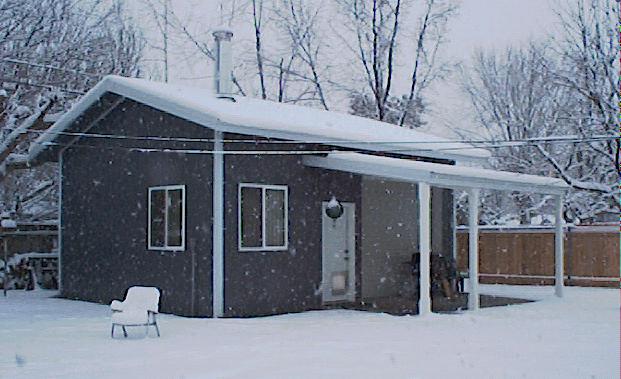
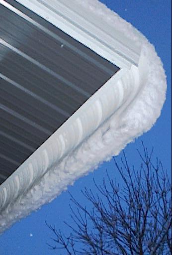
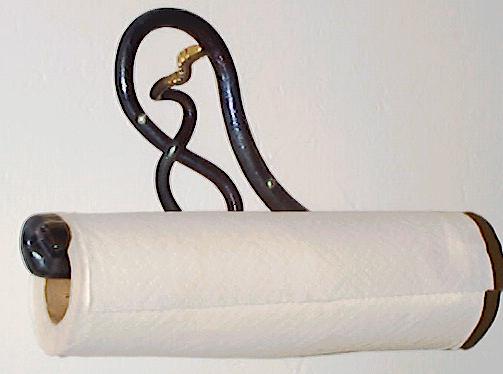
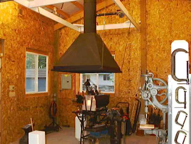
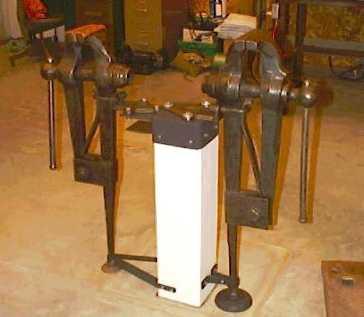
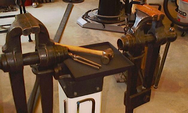
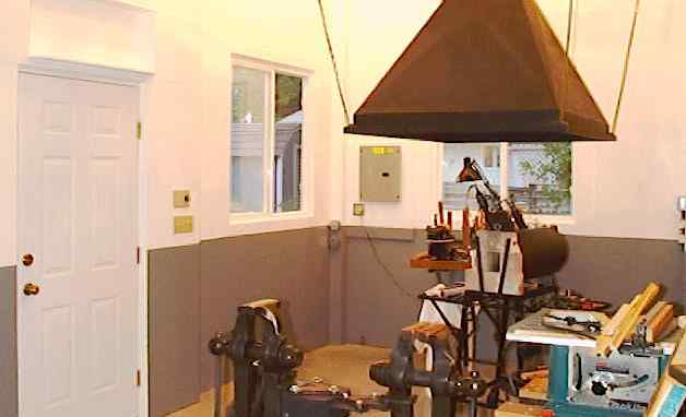
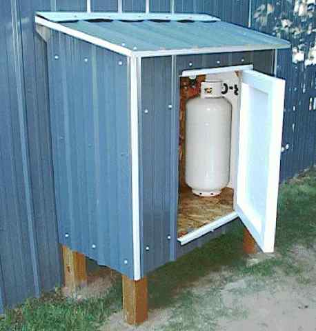
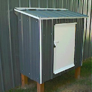
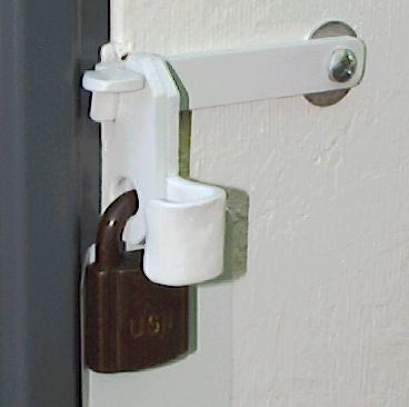
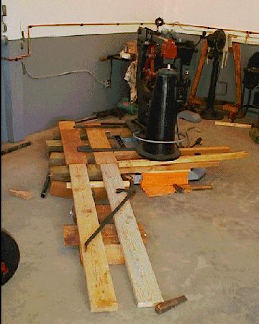
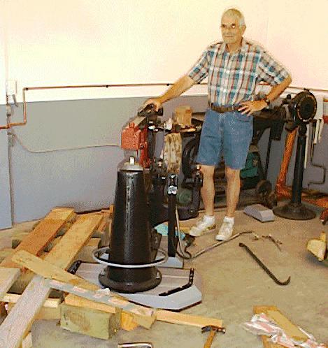
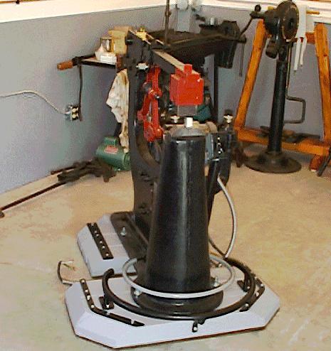
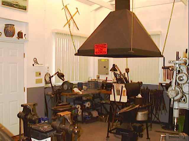
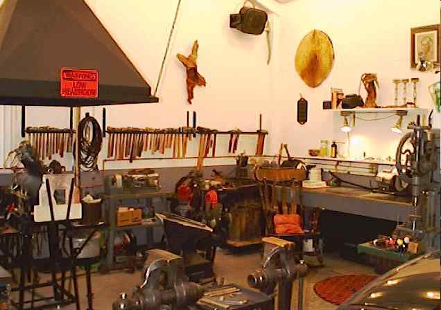
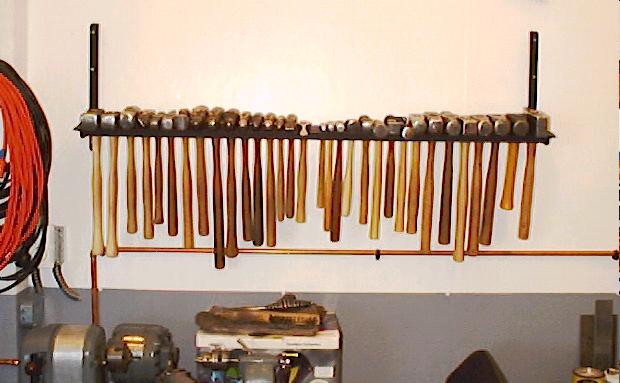
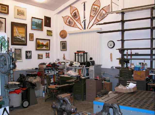
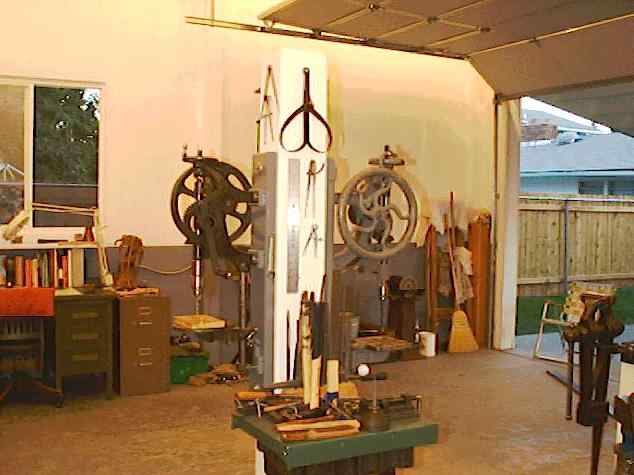
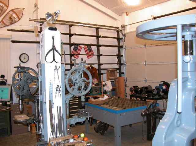
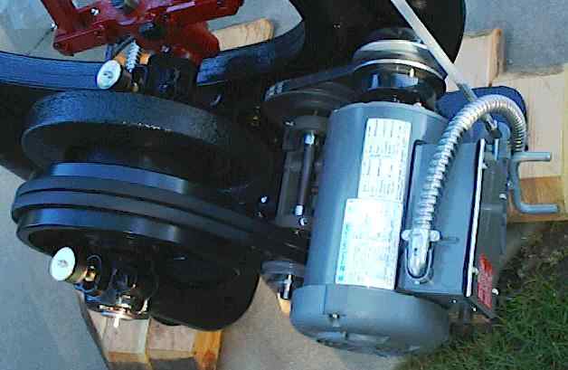
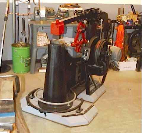
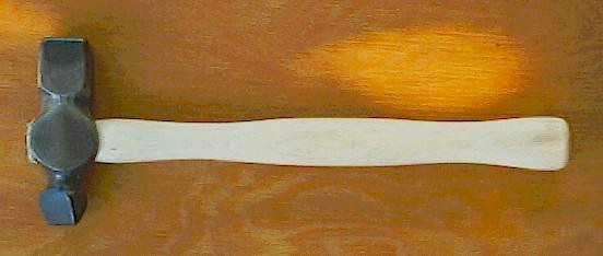
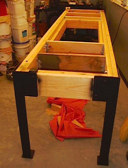
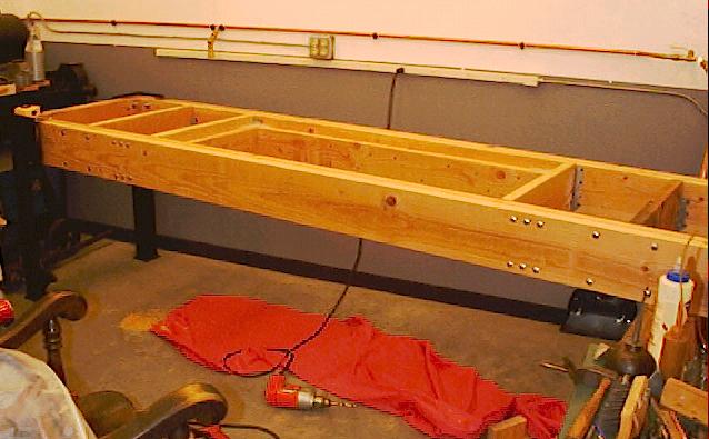
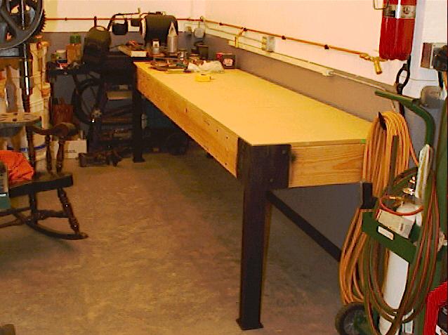
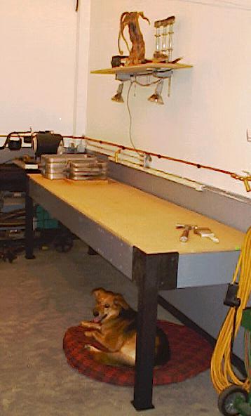
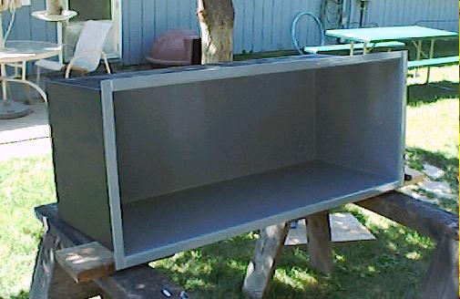
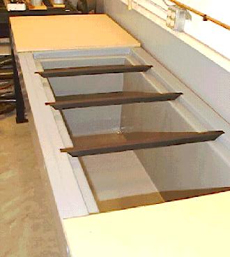
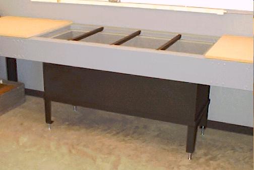
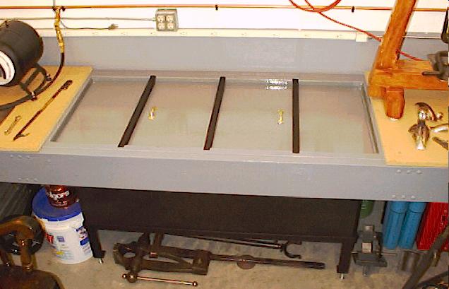
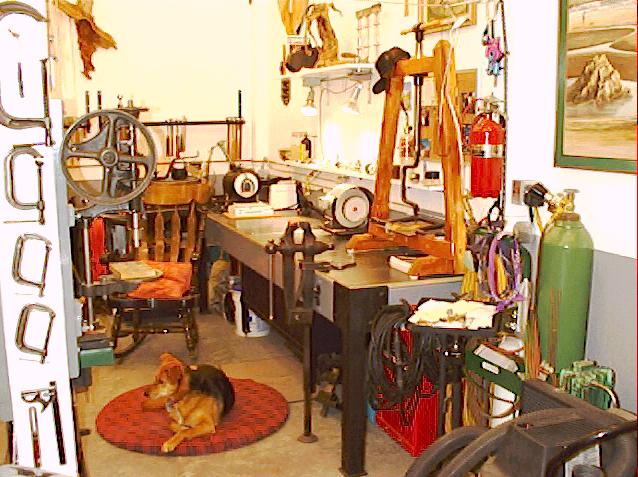
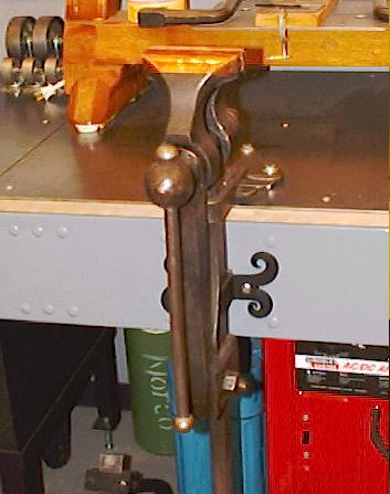
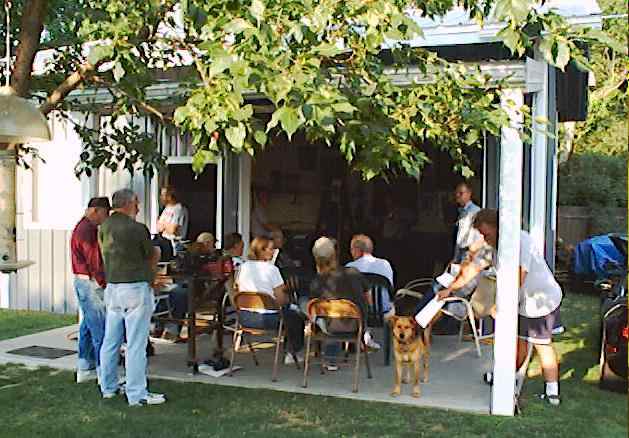
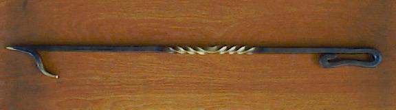
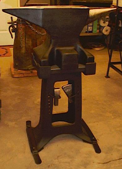
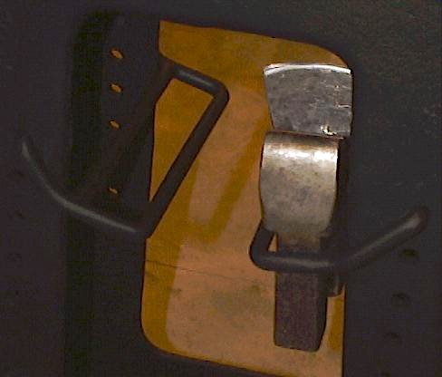
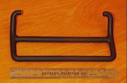
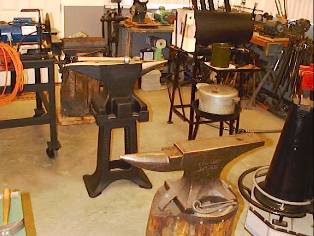
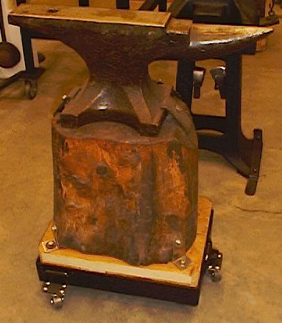
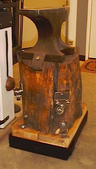
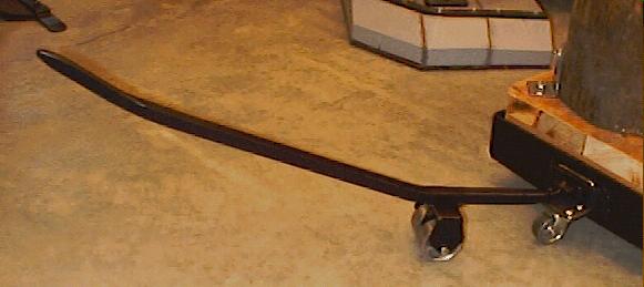