
FAQ
Ron Reil's Burner Modification
FAQ
Ron Reil's Burner Modification
Some Construction Notes:
Note: Be sure to read the "EZ-Burner" HTML
document also.
This document should be used with the burner image that was available where you obtained this file. I wanted to clarify a few things that were not clearly shown on the drawing. I will also describe one way to mount the burner in your forge.
The 3" long sleeve should be flared 1/8" in diameter over a 1-1/2" length. The opposite end should be drilled and tapped in two places, at the third points opposite the fusion ridge that runs down the center of the pipe from its welding. You will probably have to file the ridge also to get it to slide over the 3/4" burner pipe. The fusion ridge will help hold the pipe securely with only the two set screws. The threaded holes are for two set screws to lock the sleeve in place. Their size is not important, but I used very small set screws. You may attach the flare in any other manner too, its not important. When you mount the finished sleeve it should extend beyond the end of the burner barrel 1-1/2" or more. One caution, when flaring the sleeve, don't exceed a 1:12 taper or the advantages that the flare provides will be lost. If the taper is too steep the vacuum is broken and its function reduced or destroyed.
The burner tube is an 8" x 3/4" pipe nipple with the output end threads cut off. Screw it into the bell fitting as tightly as is convenient. The bell fitting has two cast in ridges down its sides that will help you get the center-line of the bell. You will need to be careful of the imports because they are rather poorly made and alignment of the ridges is often poor. File a 3/8" round slot to fit the 1/8" pipe nipple. Do this on both sides. The filed slots will maintain the jet pipe alignment.
Once the slots are in place you will need to attach it, and the way I did it was to make two "U" brackets and attach them with screws. I drilled and tapped four holes in the cast iron bell. This material works very easily. You may prefer to weld it on, but if you do, you will not be able to adjust the jet location if its not perfectly centered over the burner pipe. (See Bordeaux modification below)
I used a 1/8" pipe cap on the end of the jet pipe, but you could close the end in any number of ways, including welding or brazing on a closure of some sort. I like to keep the threaded end available to allow attachment of a gas pressure gauge if desired.
That is all there is to making one of these burners. The gas regulator can be difficult to locate since most of them out there are for RVs, and are low volume cheapo models. I finally found a superb regulator made by "Fisher Controls". It is the model 67G, with a high volume gas/liquid output range of 0-100 psi. It states in the instruction sheet that it is 5-100 psi, but works very smoothly from 0 on up. The advantage of this regulator over the cheaper models is the smooth adjustment, and the large number of turns required to adjust the pressure. This allows very small "tweaks" of the pressure to be done. I highly recommend this regulator. It will put out 1,150,000 BTU/Hr in propane. The burner will produce up to 200,000 BTU per hour.
Note: The 67G regulator discussed above is no longer available (21 Oct 98). It has been replaced with a family of 67G regulators which break the 5-100 psi range up into three separate ranges, one of which, the model 67 is 3-20 psi. See your local dealer for more information, or contact "Centaur Forge" at (414) 763-9175. I believe their price is $28.
This burner will burn lean, oxidizing environment in the forge, so you will have to adjust the intake air volume with some kind of intake air choke of your own design. Another alternative is to further tweak the jet diameter. I started with a #60 jet, but adjusted it up to a #57. At least one other blacksmith has increased the jet from a #60 to a #58 with good results also. By going to a larger diameter, jet the noise decreased greatly, and the heating changed from a spot heater to a more general wide area heater. The entire inside of the forge became more evenly heated, and it is burning a more nearly neutral flame than earlier, perhaps a little reducing if anything. It is better to have the burner burn lean initially so you can easily adjust the forge environment by simply reducing the air intake volume. It is much more difficult to go the other way.
I have set up the plumbing for the propane supply line from the tank to include a quick disconnector, and a "Tee" with high quality ball valves on each side of the "Tee". This way I can use either burner, or both, in the forge as desired. If you use a quick disconnect be sure and put the valved side on the supply end, and not on the forge end. That way if you disconnect it with the gas pressure still on it will not blast out raw propane. I purchased all industrial weight fittings and propane supply hose. I don't think the cheap stuff for barbecues, or other home use, is really suited to a forge application. If something fails you are right in the path of destruction, with a red hot forge right in front of you. It costs a little more, but the security it affords is worth it. I don't think it wise to "poor boy" a pressurized gas system. I have roughly $250 in the propane tank, regulator, hose and fittings. I bought a 10 gallon propane supply tank, and will get another one the same size. I figure I will hook them in parallel and run one until it gets too cold and then just switch over to the other using a yoke hook-up. By simply turning the two tank valves at the same time the tanks will be switched over. While the second tank runs the first one can warm up again. If I like this forge as much as I think I will, I may get a 250 gallon propane tank and have the local supply company keep it serviced for me. They will service 200 gallon and up.
Well, that about sums up the work I have done so far. I will add to this when the final forge is up and running. Building four "cheap" $5 burners has certainly cost me a lot....grin. I guess if you already have the tanks and regulator you are home free.
Tuning Your
Burner:
Note: Although the following description
applies chiefly to the
old Reil and EZ burners, much of it can be applied to others as well.
Burners
such as the Side-arm burner, that have an axially fixed jet tube, do
not
require any axial alignment. You will have to use your own judgment as
to
what applies to your particular burner design. In the newer designs,
the
nozzle position is far more critical than the jet location in producing
a
stable flame over a broad pressure range.
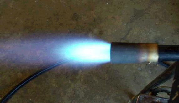
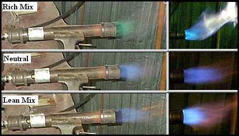
Although this is covered elsewhere, I will go over it here as well. To tune your burner you will need to remove it from the forge and work in open air. Choose a safe location so as not to set fire to the house while concentrating on the end of the burner. The first step is to align the the jet tube to inject the gas stream directly down the center axis of the bore of the burner tube. With the running burner clamped in a vise, or held in some other fashion, loosen the jet tube locking mechanism and carefully rotate it left or right while listening to the roar, and watching the flame. (Note: When you loosen the lock on the jet tube be sure you are holding on to it securely so it doesn't suddenly rotate and blast you in the face with burning propane.) (A useful tip that was passed to me about tuning the jet involves connecting the jet tube to a source of water, like a garden hose, and use the jet of water to perfectly and safely align the jet. If you are using a Tweco tip this becomes very easy.) If the jet is aimed to the side of the burner tube the flame will indicate it by being deflected to one side or the other. Locate the centered position, where the flame has a distinct loud roar, and is well centered. At the same time you will need to slide the jet tube in or out of the bell fitting jet tube mounting holes to locate center in that axis also. When you have attained the best possible centering of the jet, based on sound and flame position, lock it down securely so it can't move due to forces applied by the propane supply hose. The flame should look like the image shown in my Design page. Also be sure to study the flame images in this image to set yours for a neutral burn.
Following the tuning of the jet tube you will need to tune the flared or straight sided nozzle. This is done by releasing its set screws so you can slide it in or out on the burner tube. Move it out, and as you do so find the location where you can achieve the maximum gas pressure without blowing out the flame. You will probably end up with a nozzle exposure of somewhere between 1-1/4" and 1-1/2". This establishes your high pressure end point, and you should be able to run pressures up to 30-50 psi with this nozzle setting, perhaps higher. Mark or measure its location for later use. Now slide the nozzle in, reducing its exposure, and find the position where the flame goes out while running at a minimal pressure. You may find it goes right to the end of the burner tube, but probably not. When you locate this low pressure end point, simply adjust your nozzle for a position midway between the two extreme points you have determined.
Burners are very individual due to various small differences in their construction. If your burner does not want to cooperate exactly as I have outlined in the paragraph just above, that is not unusual. If you set your burner nozzle at an exposure of an inch or so it should perform reasonably well., but with everything adjusted properly it should run well with gas pressures up to at least 30 psi or more, and if a flared nozzle is used, it should allow you to reduce the gas pressure down to near 1 psi before it begins to pulsate or begins "huffing". Play with it until you get the best operating range possible, lock the nozzle in place, and then it will be ready to return to the forge. It should then perform well for you. If you have further problems, they will probably be related to the forge and not the burner, such as back pressure, or the shape of the hole through the Kaowool.
A very fine idea was proposed to me by Garry Jackson, regarding an alternate and better way to tune the jet tube. He connected his burner's jet tube inlet opening to a hose and used the water jet streaming out of the jet opening to easily center the stream down the center of the burner tube. This is a superb way to do it because it is a concrete solid visual method to determine with certainty the exact adjustment point, and also due to the safety factor. There will not be the danger of the jet tube rotating while its burning and blasting you in the face with burning propane. Give consideration to this alternate method of aligning the jet. It is an excellent suggestion. Thanks Garry.
An Update:
I have now used my system for several years, and have discovered it to
be
much more miserly on fuel use than I expected. I did buy another 10
gallon
tank, but now feel that it was pretty much a waste of my money. The
burners
use fuel so sparingly that the problem of temperature drop has never
materialized. I even ran the forge at 20 below zero one evening because
I
needed to make a billet of Damascus, and after running it for several
hours
the tank was still supplying gas at a workable pressure. I did notice a
pressure
decrease while I was running it however and adjusted the regulator
accordingly.
Please consider using a Tweco Tip in your burner. It will make it far more efficient, and will enable the burner to produce higher temperatures. Also, before deciding on your final choice of burner design, be sure to review the information available about the new Mongo Series of burners. These are much higher performance burners, but present some unique hazards and considerations, so be fully aware of the pros and cons of this burner series before selecting one for your forge.
Bordeaux Modification:
Robert Bordeax provided a wonderful modification to the method I
provided
in the drawing for attaching the 1/8" jet pipe to the bell fitting. His
method
employs drilling a hole through both sides of the bell, next to the
lip,
that will just allow the jet pipe to slide through. The pipe is then
held
in position by drilling two additional holes through the lip into the
holes
previously drilled for the jet pipe. These are dimensioned as
convenient
for the builder, and are threaded to accept a set screw in each to hold
the
jet pipe in position. This method eliminates the tedious fabrication of
the
"U" brackets and also the drilling and tapping of two holes. This
method
also will be far more robust, and has the advantage that it places the
jet
closer to the ventouri constriction, a more efficient location. I
highly
recommend this method of construction. Thanks Robert. :)
NOTE: Although I have not addressed every tiny detail of building this burner, such as set screw dimensions, and screw and tap sizes, they are things that have no operational importance, and can be varied to suit the builder. Just use what you have laying around your shop. Also, there is no "right or wrong" way to build it. If you think that perhaps something else may work in place of "my way", by all means try it. Let us know how it goes, because that's how we make progress with these designs. There are at least four of us actively working on burner design improvements, and the more who get into the act the better chance we have of discovering a truly revolutionary burner design such as the Bordeaux modification above. Thanks. :)
Some additional comments:
I have received a number of e-mails regarding two things that I would
like
to clear up here. A number of guys have asked how to do the flare. It
is
one of those cases where you need a forge to build a forge. If you will
heat
the burner tip piece, the nozzle, to a red heat, and slide it over any
piece
of round bar close to the inside diameter of the pipe, you can easily
flare
it by working it gently with a hammer all around the circumference of
the
nozzle. Just be sure you don't overdue it and make the flare too big.
The second item concerns the drill diameters for the jets. The numbered drills refer to a set of drills numbered from 1 to 80. The #1 is the largest, and the #80 the smallest. The jet diameters that you are probably interested in range from a #57 to a #60, but I have included more of the table in case you wish to go beyond that range. The following are conversions to inches for these drill numbers.
#50 = 0.0700"
#51 = 0.0670"
#52 = 0.0635"
#53 = 0.0595"
#54 = 0.0550"
#55 = 0.0520"
#56 = 0.0465"
#57 = 0.0430"
#58 = 0.0420"
#59 = 0.0410"
#60 = 0.0400"
#61 = 0.0390"
#62 = 0.0380"
#63 = 0.0370"
#64 = 0.0360"
#65 = 0.0350"
#66 = 0.0330"
#67 = 0.0320"
#68 = 0.0310"
#69 = 0.0292"
#70 = 0.0280"
These drills are very small, and can't be gripped by the average drill chuck, so you may need to obtain a special chuck to grab them with, that will mount in your existing chuck. They are small and inexpensive. Get extra drills too, because they break very easily in use. I use my Fordum flex shaft tool, fitted with a three jaw chuck to drill these holes, and the high speed it is capable of really helps.
If you are working with TWECO 14T jet tips, the following information may be of help too. This is a little conversion table of nominal jet diameters to actual orifice diameters in inches. Use actual diameter for all burner design work.
Nominal Actual
0.023" 0.031"
0.030" 0.038"
0.035" 0.044"
0.052" 0.064"
0.062" 0.073"
A few additional comments regarding the flared nozzles..... Many guys seem to think they need to machine them, or get them machined. This is easy blacksmith work, so if you can find a source of heat prior to building your forge, and even a fireplace or BBQ will work, take a heat on the end of the pipe section and simply work it gently with the hammer over any piece of round rod held in the vise that is slightly smaller than the opening in the pipe. You may need to take several heats to get the job done. The end of the pipe section will quickly expand to form the flare you need. It takes me about 5 minutes to make a flare in this fashion, and it is virtually perfect to the eye. The next comment concerns the material. If you can, make it out of stainless steel. It will last far longer than mild steel pipe. The severe environment in the forge causes rapid degradation of mild steel. Lastly, and probably most important, the 1:12 rate of flare is critical. DON'T try any other way to do this, including using a pipe reducer bell fitting. There is a lot more to this design than meets the eye. If you don't fully understand the dynamics of this system please don't attempt to change it. You will only waste your time and mine. Consult with me if you have a question. Thank you. :-) Warning! Be very careful quenching the hot pipe. It will cause the water in it to instantly turn to steam, and blow boiling water out the uper end on to your hand, arm, or in your face. If you are not familiar with forging pipe, it would be best to let it cool without quenching.
Another Good Intake Design:
I thought about another method of locking down the jet tube, other than
those
listed above. I played with it a little bit and then discarded the
idea,
until I was e-mailed the same idea several times by different guys who
also
thought about it and decided it would be a good way to simplify
building
this burner. I finally decided to build a burner using this technique,
and
it works quite well. I will most likely use this method from now on
because
it provides several additional advantages over and above simplicity of
construction.
Instead of drilling and tapping holes, and using set screws to lock in your jet tube, simply use a 1-1/2" bell on the burner tube and a short section of the threaded end of a nipple to fit it. With the jet tube in place, as in the "Bordeaux Modification", just screw down the section of nipple until it locks the jet pipe in place. You must use the 1-1/2" bell however because of the loss of open area in the mouth caused by the nipple. Use of a 1-1/4" bell will cause too much intake restriction and your burner will be oxygen starved and run cool.
By doing it this way you will have a short section of pipe, about 1", sticking above the bell which will allow easy installation of an axial mounted screw down choke, or will allow easy installation of a small blower or air supply system if you so desire. I just built a forge around one of these burners and found it works very well. The only disadvantage I found was the tendency for the nipple section to try to rotate your jet tube when you are tightening it down. If you file the contacting surface of the nipple so that it contacts both sides of the jet pipe equally, this tendency is reduced or eliminated. Also applying a touch of grease between the jet tube and nipple edge helps to reduce the turning force created by the dragging action of the nipple on the jet tube. I drilled two holes opposite each other on the exposed lip of the nipple to allow a small steel rod to be inserted and used to tighten the nipple section down on the jet. That way you don't trash it with the sharp teeth in a pipe wrench. Overall, this burner is the cleanest looking and easiest to make so far.
Mounting the Burner: There are two important considerations when mounting the burner. The burner nozzle must be sealed tightly in the wall of the forge refractory to prevent gas leakage past the nozzle, and the nozzle must not be allowed to protrude into the forge chamber, or is will be burned or melted off.
I always use at least 2" of Kaowool in my forges. This makes mounting the burner relatively easy. I make a penetration through the exterior layer of Kaowool for the nozzle by cutting a cross or "X" in the Kaowool and forcing it over the nozzle. This will seal it tightly, preventing any gas leakage in either direction. I then install the second layer of Kaowool, and after its all finished, but before I apply ITC-100, I find the location where the burner nozzle is, and cut another "X" directly in front of the nozzle opening. I don't make the length of the cuts any longer than an inch.
Using my finger, I force the Kaowool open and form it as much as possible. This is difficult because the Kaowool wants to close the hole. Once I have created the beginnings of a hole, I use a turned hardwood cone shaped mandrel, or "plug," which I force into the opening to open it up to the diameter of the opening of the nozzle. The taper of the plug is about twice the taper of the nozzle to help the Kaowool take a set. Once I have forced it all the way to the point of refusal, because its fully contacting the inner nozzle edge, I leave it there overnight. This allows the Kaowool to take a set to a small degree. I then remove the wooden mandrel and clean up the hole, pulling the loose fibers out of the nozzle and tucking them in as much as possible around the outside of the nozzle. The "plug" goes back in, and I leave it there until I am ready to fire it for the first time. By replacing the plug each time I am done using the forge, for a couple weeks, the Kaowool will take a permanent set and will no longer try to close in around the nozzle. Ideally, the taper of the hole will be a continuation of the taper of the nozzle, but it is usually greater. It seems to work just fine even with the oversize hole in the Kaowool. When I build forges that are sold and shipped, I leave a turned wooden plug in place in the hole when I pack it up for shipment.
Ron Reil
Boise, ID
Note: I no longer can provide help or support for forge or
burner construction.
Thank you.
The Full Site Map - Lists All Pages on This Site
Page By: Ron Reil
Edited With: AOLpress
©Golden Age Forge
23 Nov 07