
©Golden Age Forge

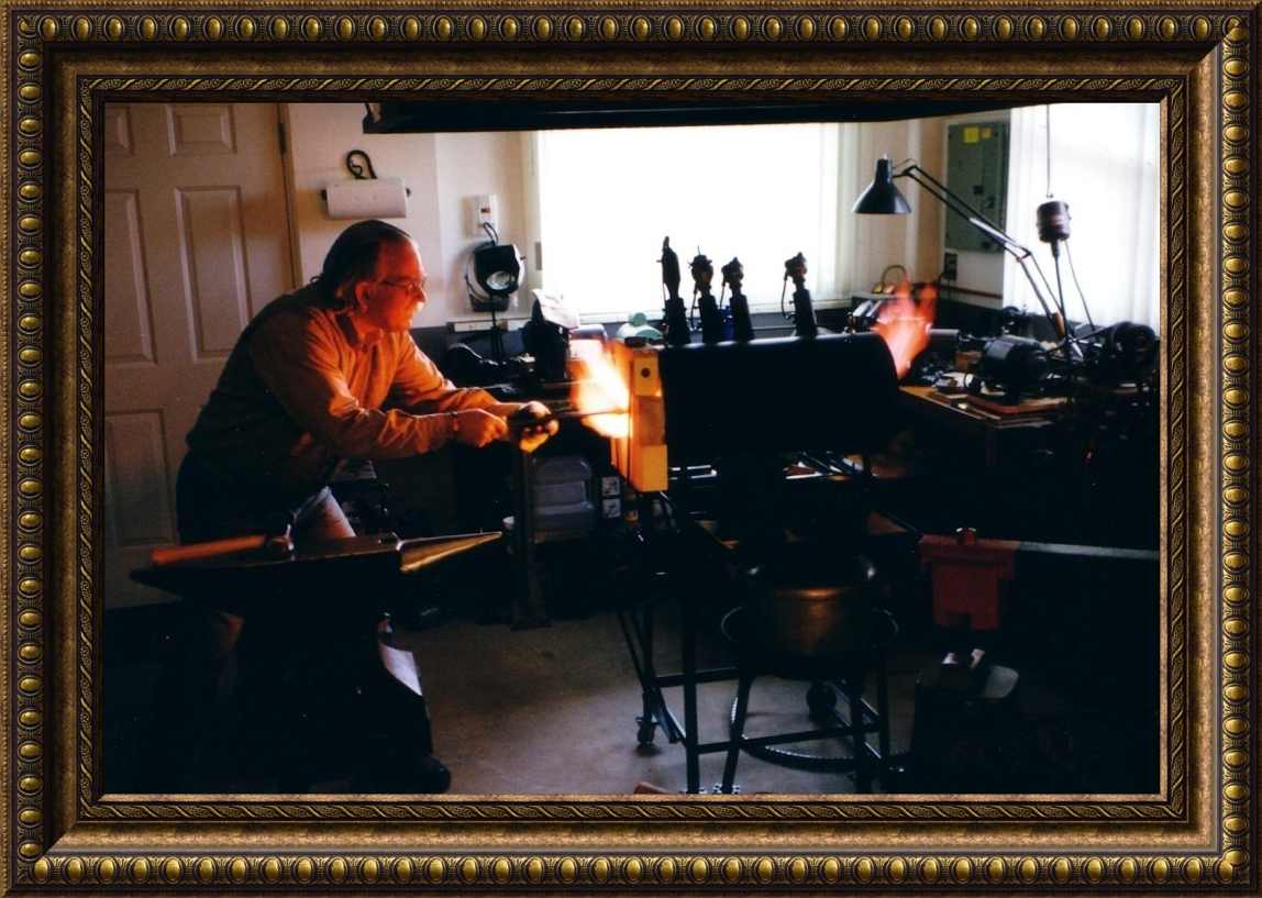
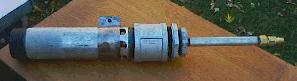
I am about to forge-weld a Spontoon pipe-ax head.
(This excellent image was taken by my apprentice, Kevin Brown)
A New Addition to My Shop - Out of this
world!
This is a 64 pound nickel-iron meteorite from Argentina that
fell about
4000 years ago!
Contact me by phone: (208)
462-4028
Note: Due to spam problems I no longer post my e-mail address.
![]()
![]() I provide the
following information as a service
to the blacksmithing community. Although the designs I employ in
building
my burners and forges are safe and reliable in the way that I use them,
the
same may not be the case for you. You assume all risk in
using this
information, or any other information on my site. Other
designs that
I have posted here have been submitted by other smiths, and I have no
experience
with most of them. Use care and good sense in using any of these
designs.
Get help from a knowledgeable smith if you are new to this work. Don't
take
chances, because these tools can cause injury, blindness, or even
death,
if used improperly. Also, be sure you are in a well ventilated space
(see the Nighthawk CO
& explosive gas
detector paragraph), or better yet, work outside.
Additionally, never
operate a forge that is connected directly to a propane tank located
near
a forge, or indoors. An emergency pressure valve release
could instantly
place you in the middle of a fireball. Follow all local codes regarding
indoor use of propane. I believe indoor use of a propane tank
violates
code everywhere in North America, and most of Europe. A new concern has
arisen
with the introduction of the "Mongo Burner Series." Please read
carefully
all the information in the separate "Safety
Warnings and Considerations" information which heads the
"Mongo Burner
Series" section. Thank you.
I provide the
following information as a service
to the blacksmithing community. Although the designs I employ in
building
my burners and forges are safe and reliable in the way that I use them,
the
same may not be the case for you. You assume all risk in
using this
information, or any other information on my site. Other
designs that
I have posted here have been submitted by other smiths, and I have no
experience
with most of them. Use care and good sense in using any of these
designs.
Get help from a knowledgeable smith if you are new to this work. Don't
take
chances, because these tools can cause injury, blindness, or even
death,
if used improperly. Also, be sure you are in a well ventilated space
(see the Nighthawk CO
& explosive gas
detector paragraph), or better yet, work outside.
Additionally, never
operate a forge that is connected directly to a propane tank located
near
a forge, or indoors. An emergency pressure valve release
could instantly
place you in the middle of a fireball. Follow all local codes regarding
indoor use of propane. I believe indoor use of a propane tank
violates
code everywhere in North America, and most of Europe. A new concern has
arisen
with the introduction of the "Mongo Burner Series." Please read
carefully
all the information in the separate "Safety
Warnings and Considerations" information which heads the
"Mongo Burner
Series" section. Thank you.
![]() An
additional item that should be of interest to you is
obtaining an
explosive gas/CO detector for your working space.
Mark Manley, of
"Manley Metal Works,"
Silverton, Oregon, provided a short piece of very important information
in
the Winter 2000 issue of "Hot Iron News" that I think needs to be
passed
on to a wider audience. There is a very reasonably priced digital
read-out
combination explosive gas and CO detector available in local hardware,
building
supply, and other stores. I was concerned about having a CO monitor in
my
shop, even though I have a very efficient induced draft hood in my
shop.
The detector is made by
"Kidde Safety"
and
is called the "Nighthawk." I will not go into the
specs for the instrument
here, they are available on their web site, but I will say that it is a
very
finely designed and built instrument. It runs on 110 VAC, and has a 12
VDC
back-up. It plugs directly into an outlet, or the transformer plug
detaches
for remote mounting up to 6' from the plug. You can easily check your
CO
level with a quick glance at the digital read-out, and if it detects
any
kind of flammable gas it will instantly sound an audible alarm, and the
word
"Gas" will show on the digital display. If it detects CO, it will sound
a
different audible alarm and display the PPM level. Also, you will know
it's
operating because the blinking decimal point in the digital read-out
indicates
it's operating and sampling the air in your shop.
An
additional item that should be of interest to you is
obtaining an
explosive gas/CO detector for your working space.
Mark Manley, of
"Manley Metal Works,"
Silverton, Oregon, provided a short piece of very important information
in
the Winter 2000 issue of "Hot Iron News" that I think needs to be
passed
on to a wider audience. There is a very reasonably priced digital
read-out
combination explosive gas and CO detector available in local hardware,
building
supply, and other stores. I was concerned about having a CO monitor in
my
shop, even though I have a very efficient induced draft hood in my
shop.
The detector is made by
"Kidde Safety"
and
is called the "Nighthawk." I will not go into the
specs for the instrument
here, they are available on their web site, but I will say that it is a
very
finely designed and built instrument. It runs on 110 VAC, and has a 12
VDC
back-up. It plugs directly into an outlet, or the transformer plug
detaches
for remote mounting up to 6' from the plug. You can easily check your
CO
level with a quick glance at the digital read-out, and if it detects
any
kind of flammable gas it will instantly sound an audible alarm, and the
word
"Gas" will show on the digital display. If it detects CO, it will sound
a
different audible alarm and display the PPM level. Also, you will know
it's
operating because the blinking decimal point in the digital read-out
indicates
it's operating and sampling the air in your shop.
![]() I bought one of
these
instruments for my shop, and was so impressed with it that I went down
and
bought a second one for my home, which has natural gas heat, gas hot
water,
and a natural gas fireplace insert. I priced CO detectors on the
McMaster-Carr
web site, and they alone were $170, where this combination instrument
is
only $59 at my local Home Depot. Considering how deadly CO can be, this
instrument is very inexpensive, well worth the investment, and it may
well
save your life. After Mark installed his "Nighthawk," he discovered
that
he had been exposing himself to CO levels of 30-160 PPM for a long time
while
running his forge! Thanks for the tip Mark.
I bought one of
these
instruments for my shop, and was so impressed with it that I went down
and
bought a second one for my home, which has natural gas heat, gas hot
water,
and a natural gas fireplace insert. I priced CO detectors on the
McMaster-Carr
web site, and they alone were $170, where this combination instrument
is
only $59 at my local Home Depot. Considering how deadly CO can be, this
instrument is very inexpensive, well worth the investment, and it may
well
save your life. After Mark installed his "Nighthawk," he discovered
that
he had been exposing himself to CO levels of 30-160 PPM for a long time
while
running his forge! Thanks for the tip Mark.
Note: There has been a recall of Kidde Safety "Nighthawk" gas and CO detectors. This does not affect any detectors sold after the date that I posted the above information, however you may check your unit by going to http://www.cpsc.gov/cpscpub/prerel/prhtml99/99082.html.
A Word About Obtaining My Help
![]() I am no longer
able to offer my support to help solve problems you may have with your
burners or forge. I have reached the point that something has to give.
Two to three hours a night answering questions has brought my metal
working each evening of the week to a stand still. I will continue to
update my blacksmithing pages, and will now also have the time to clean
out all the outdated and conflicting information in my pages, however,
I will no longer be able to troubleshoot your system. I still want to
receive your e-mails if they do not pertain to forge or burner
problems. If you build your burner to the design specs and information
shown and discussed on my pages, including in the Troubleshooting
Document and FAQ, your burner should work well. If it doesn't, then its
not built correctly, and you will need to make some adjustments after
looking through the available information. The best thing to look at
when fine tuning your burner are the various flame
images I have posted. If yours looks like these images, you have it
right. Here are a few helpful links.
I am no longer
able to offer my support to help solve problems you may have with your
burners or forge. I have reached the point that something has to give.
Two to three hours a night answering questions has brought my metal
working each evening of the week to a stand still. I will continue to
update my blacksmithing pages, and will now also have the time to clean
out all the outdated and conflicting information in my pages, however,
I will no longer be able to troubleshoot your system. I still want to
receive your e-mails if they do not pertain to forge or burner
problems. If you build your burner to the design specs and information
shown and discussed on my pages, including in the Troubleshooting
Document and FAQ, your burner should work well. If it doesn't, then its
not built correctly, and you will need to make some adjustments after
looking through the available information. The best thing to look at
when fine tuning your burner are the various flame
images I have posted. If yours looks like these images, you have it
right. Here are a few helpful links.
Note: If you e-mail me, please be sure your e-mail in "txt" (text) format, not html. I am now averaging two to three virused e-mails each time I download my e-mail, so I have to be very careful. If your e-mail is not in "txt" format I will most likely delete your e-mail without opening it in order to protect from possible virus infection. It's certainly sad that we have idiots in our society that feel they must cause such problems.
Forge & Burner Troubleshooting Document
1) T-Rex Flame Image - Ideal Neutral Flame
2) Side-arm Burner Flame Using Temporary Cast Iron Test Nozzle - Slightly Reducing Flame
3) Another Flame Image - Oxidizing Flame
![]() The bottom three
flame images give you views of burner flames adjusted to 1) neutral, 2)
slightly reducing, and 3) strongly oxidizing. The burners have nothing
to do with it, just the choke settings. All of these images could have
been done with the T-Rex, or Side-arm burners. At your high end gas
pressure, if you have achieved a flame similar to the oxidizing flame
shown in the bottom image, #3, you will then have full control over the
burner flame across the full pressure range. This will allow you to
achieve oxidizing, neutral, or reducing, flames as needed by simply
adjusting the choke. You will then have a properly functioning burner.
The bottom three
flame images give you views of burner flames adjusted to 1) neutral, 2)
slightly reducing, and 3) strongly oxidizing. The burners have nothing
to do with it, just the choke settings. All of these images could have
been done with the T-Rex, or Side-arm burners. At your high end gas
pressure, if you have achieved a flame similar to the oxidizing flame
shown in the bottom image, #3, you will then have full control over the
burner flame across the full pressure range. This will allow you to
achieve oxidizing, neutral, or reducing, flames as needed by simply
adjusting the choke. You will then have a properly functioning burner.
My Home
Page, & Pages on This Site
The Full Site Map - Lists All Pages on
This Site
![]() Visit my newest page, my "New Home and
Shop Page"
Visit my newest page, my "New Home and
Shop Page"![]()
Construction of the Freon Tank Mini-Forge
Note: "The Best of Theforge" is a collection of posts to "theforege" covering a great many blacksmithing subjects. It is made up of three separate files that are all hot linked and indexed. If you want to know what Superquench is, or the composition of a railroad spike, this is were you will find it. I have a lot of work in these files, I hope you will find my time was well spent.
The
Best of "Theforge" - a Zipped Download of All Three Files
-or-
The Best of Theforge -
Vol 1
Subject Index for the Design Pages
(Small font indicates a subsection.)
Page #1
The Reil & EZ Burners (These are the standard burners)
-Proper Nozzle Placement in the Forge
-Safety Warnings and Considerations for the Mongo Burners
-Micromongo & Nanomongo Burners
Page #2
Sources for Refractories, Burner Nozzles, & T-Rex Burners
-Obtaining Premade Burner Flares
Download the BTU Output Calculator
How Hot Can These Burners Get?
Some Additional Gas Forge Designs, 1 through 4
-Sandia Recuperative Forge Design
Additional Coal Forge Designs & Brake Drum Forges
A Preface for All Burners on This
Page
The "TWECO 14T Tip" Modification
![]() Work
by
Michael Porter
in Seattle has resulted
in a powerful modification that I recommend you apply to any of the
burner
designs on my pages. Instead of simply drilling the desired jet hole in
the
burner tube, you can achieve far superior results by drilling and
tapping
the jet hole location to take a 1/4"x 28 threaded "TWECO 14T" copper
tip,
available at your local welding supply shop. There are a variety of
these
tips in various jet diameters and external configurations available.
You
should try to obtain the Tweco tip configuration that measures 1-1/2"x
1/4,"
and has a long tapering nozzle tip. With this arrangement you can
easily
experiment with various tip openings simply by switching them as
desired.
Once you determine which tip performs best for your particular
application,
then you should silver solder it into place to prevent any possible gas
leakage
past the threads. Because of the high temperatures that the jet tip may
encounter, due to occasional chimney effects, you should not use any
other
lower temperature process, such as Teflon tape or soft lead solder.
Another
comment that applies if you are modifying the "Reil or EZ Burners"
regards
the bell diameter. The increased suction created by this tip
modification
will require that you increase the intake bell to a 2" diameter, or you
will
not get enough intake air to achieve a balanced burn.
Work
by
Michael Porter
in Seattle has resulted
in a powerful modification that I recommend you apply to any of the
burner
designs on my pages. Instead of simply drilling the desired jet hole in
the
burner tube, you can achieve far superior results by drilling and
tapping
the jet hole location to take a 1/4"x 28 threaded "TWECO 14T" copper
tip,
available at your local welding supply shop. There are a variety of
these
tips in various jet diameters and external configurations available.
You
should try to obtain the Tweco tip configuration that measures 1-1/2"x
1/4,"
and has a long tapering nozzle tip. With this arrangement you can
easily
experiment with various tip openings simply by switching them as
desired.
Once you determine which tip performs best for your particular
application,
then you should silver solder it into place to prevent any possible gas
leakage
past the threads. Because of the high temperatures that the jet tip may
encounter, due to occasional chimney effects, you should not use any
other
lower temperature process, such as Teflon tape or soft lead solder.
Another
comment that applies if you are modifying the "Reil or EZ Burners"
regards
the bell diameter. The increased suction created by this tip
modification
will require that you increase the intake bell to a 2" diameter, or you
will
not get enough intake air to achieve a balanced burn.
![]() An additional consideration that I need to mention, and which
is covered
in detail in the "Safety Warning"
section at the top
of the Mongo Burner information, regards UV radiation hazard. The Tweco
tips
increase the efficiency of the burners and their output temperature. In
the
Mongo burners the temperatures are up into the middle UV temperature
color
range, and it is possible to get "flash burns" from the light coming
out
of the forge. Be aware of this potential hazard with any burner you
modify
to use this tip. UV radiation is very damaging to eyes and
skin.
An additional consideration that I need to mention, and which
is covered
in detail in the "Safety Warning"
section at the top
of the Mongo Burner information, regards UV radiation hazard. The Tweco
tips
increase the efficiency of the burners and their output temperature. In
the
Mongo burners the temperatures are up into the middle UV temperature
color
range, and it is possible to get "flash burns" from the light coming
out
of the forge. Be aware of this potential hazard with any burner you
modify
to use this tip. UV radiation is very damaging to eyes and
skin.
Be sure to read the FAQ that goes with this design also.
![]() The
burner design above
is my modification to the well known "Aussie" burner, as
designed by
various smiths, some noted on the drawing. The "Reil Burner" is a
superior
burner in all respects. It will sustain a controlled flame with propane
gas
pressures of over 50 psi. The cost of building it averages about $5 US,
and
it is constructed of all "off the shelf" plumbing parts, available in
any
hardware store. The FAQ
explains its
construction, but is not a detailed step by step instruction
sheet.
It is a collection of suggestions and observations that will be of use
if
you decide to build one. This document also includes a section on
tuning
your burner.
The
burner design above
is my modification to the well known "Aussie" burner, as
designed by
various smiths, some noted on the drawing. The "Reil Burner" is a
superior
burner in all respects. It will sustain a controlled flame with propane
gas
pressures of over 50 psi. The cost of building it averages about $5 US,
and
it is constructed of all "off the shelf" plumbing parts, available in
any
hardware store. The FAQ
explains its
construction, but is not a detailed step by step instruction
sheet.
It is a collection of suggestions and observations that will be of use
if
you decide to build one. This document also includes a section on
tuning
your burner.
Note: Brian Boorman has created an outstanding step by step pictorial web page showing the complete construction of a Reil Burner. If the line drawing linked above isn't enough information for you to work from, you may want to visit Brian's page. Go to http://metalcast.boorman.us and click the "Propane Burner" link. I want to thank Brian for his outstanding contribution to the metalworking community.
![]() I have now included
an additional "EZ-Burner"
design that you may
find much easier to build. It eliminates the difficulty of doing the
flare
in the nozzle, and also eliminates three of the drilled and tapped
holes.
I am not including a drawing for this modification, as it is
not necessary,
but I do have an image of the burner
if you are
interested. The "EZ-Burner" HTML document linked above should provide
all
the information you need to build this quick and easy burner. It should
only
require a couple of hours to complete it. I would like to include one
additional
note about galvanized pipe. By all means do use it
for your burner.
It will not get hot enough to bother the galvanizing over most of its
length,
and if it does, you are doing something wrong. Properly used, the
burner
should be cool enough to handle at all times, except for the 1"
diameter
nozzle piece at the end. The galvanizing will protect your burner from
rust.
If it does get hot enough at the end to burn off the coating, the tiny
amount
involved will not cause you any problems. Also, do not use any pipe
joint
compound in the 3/4" joint, it's just not necessary, or of any value.
I have now included
an additional "EZ-Burner"
design that you may
find much easier to build. It eliminates the difficulty of doing the
flare
in the nozzle, and also eliminates three of the drilled and tapped
holes.
I am not including a drawing for this modification, as it is
not necessary,
but I do have an image of the burner
if you are
interested. The "EZ-Burner" HTML document linked above should provide
all
the information you need to build this quick and easy burner. It should
only
require a couple of hours to complete it. I would like to include one
additional
note about galvanized pipe. By all means do use it
for your burner.
It will not get hot enough to bother the galvanizing over most of its
length,
and if it does, you are doing something wrong. Properly used, the
burner
should be cool enough to handle at all times, except for the 1"
diameter
nozzle piece at the end. The galvanizing will protect your burner from
rust.
If it does get hot enough at the end to burn off the coating, the tiny
amount
involved will not cause you any problems. Also, do not use any pipe
joint
compound in the 3/4" joint, it's just not necessary, or of any value.
![]() I used four Reil
burners on my 24" long cylindrical
forge, but two
or three are all that is necessary, and two will probably be enough in most
cases.
I live at an elevation of 2300 feet, and I can easily weld with only
one
burner running at 6 psi propane pressure. They are also being used
successfully
at over 7000 feet elevation, and they can weld easily at that
elevation.
If you would like to see more images of this forge, please go to my
Forge and
Foundry Page.
Thank you.
I used four Reil
burners on my 24" long cylindrical
forge, but two
or three are all that is necessary, and two will probably be enough in most
cases.
I live at an elevation of 2300 feet, and I can easily weld with only
one
burner running at 6 psi propane pressure. They are also being used
successfully
at over 7000 feet elevation, and they can weld easily at that
elevation.
If you would like to see more images of this forge, please go to my
Forge and
Foundry Page.
Thank you.
![]() Use of Natural Gas:
You may use this burner for natural gas applications, but will have to
increase
the jet size in order to do so, and you will require 10-20 psi natural
gas
pressure. I know of at least two smiths currently using them with
natural
gas, but I do not know the jet diameters they are using. If you use
this
design for natural gas I would very much appreciate knowing your jet
size,
so I can add that information to this page so others may benefit from
your
work. Please contact me at (208) 462-4028. Thank you.
Use of Natural Gas:
You may use this burner for natural gas applications, but will have to
increase
the jet size in order to do so, and you will require 10-20 psi natural
gas
pressure. I know of at least two smiths currently using them with
natural
gas, but I do not know the jet diameters they are using. If you use
this
design for natural gas I would very much appreciate knowing your jet
size,
so I can add that information to this page so others may benefit from
your
work. Please contact me at (208) 462-4028. Thank you.
![]() I was contacted by
Ray Maiara
concerning the use of natural
gas. He is using natural gas at only 1/3 psi pressure, and has had to
go
to a very large "jet" size, about 1/8", and he is using a blower also,
so
this doesn't fit in the category of a venturi type burner. He has also
gone
to very large plumbing diameters, main feed of 1-1/2", and forge lead
in
of 3/4", to obtain as little restriction on the gas flow as possible.
If
you are considering the use of natural gas, contact your gas utility
and
ask them if they can provide you with a high pressure feed. My gas
company
will provide a high pressure tap off the household service, up to 80
psi,
and there is no additional service to pay for, nor is there any charge
for
the work to install the high pressure tap. I do have to buy the
additional
regulator however. It is worth your time to check into, since this
burner
will function with natural gas if sufficient pressure is available, but
again,
you will have to experiment with the jet diameter to find the proper
diameter,
given your available pressure. You must have enough pressure for the
venturi
action to operate correctly to draw the air into the bell. Remember
that
natural gas will not provide as much heat as propane, so your forge may
not
be able to forge-weld. If you use a blower and large jet diamerter you
will
be able to forge-weld easily.
I was contacted by
Ray Maiara
concerning the use of natural
gas. He is using natural gas at only 1/3 psi pressure, and has had to
go
to a very large "jet" size, about 1/8", and he is using a blower also,
so
this doesn't fit in the category of a venturi type burner. He has also
gone
to very large plumbing diameters, main feed of 1-1/2", and forge lead
in
of 3/4", to obtain as little restriction on the gas flow as possible.
If
you are considering the use of natural gas, contact your gas utility
and
ask them if they can provide you with a high pressure feed. My gas
company
will provide a high pressure tap off the household service, up to 80
psi,
and there is no additional service to pay for, nor is there any charge
for
the work to install the high pressure tap. I do have to buy the
additional
regulator however. It is worth your time to check into, since this
burner
will function with natural gas if sufficient pressure is available, but
again,
you will have to experiment with the jet diameter to find the proper
diameter,
given your available pressure. You must have enough pressure for the
venturi
action to operate correctly to draw the air into the bell. Remember
that
natural gas will not provide as much heat as propane, so your forge may
not
be able to forge-weld. If you use a blower and large jet diamerter you
will
be able to forge-weld easily.
![]() A properly adjusted
gas forge will have an air/gas mixture that will create a neutral, or
slightly
reducing, environment inside the forge. This is necessary to prevent
excessive
oxidation and scaling of the metal. With my burner design, the forge
environment
should meet that requirement if you use a #57 or #58 jet diameter. I
have
found that my forge needs no choke or intake air controls, and runs
with
a slightly reducing atmosphere as desired. If you want a very simple
and
extremely efficient burner, use the modified Aussie design. If you
build
it with the Bordeaux modification you will have the greatest
versatility
for adding a blower, or intake air controls (choke), if you feel you
need
them later.
A properly adjusted
gas forge will have an air/gas mixture that will create a neutral, or
slightly
reducing, environment inside the forge. This is necessary to prevent
excessive
oxidation and scaling of the metal. With my burner design, the forge
environment
should meet that requirement if you use a #57 or #58 jet diameter. I
have
found that my forge needs no choke or intake air controls, and runs
with
a slightly reducing atmosphere as desired. If you want a very simple
and
extremely efficient burner, use the modified Aussie design. If you
build
it with the Bordeaux modification you will have the greatest
versatility
for adding a blower, or intake air controls (choke), if you feel you
need
them later.
![]() There are an unlimited variety of forge designs, almost as
many designs as smiths, and most work well enough to do normal forging.
Probably fewer are hot enough to forge weld, but that can usually be
corrected with a little homework in proper forge design. However, every
now and again a forge comes along that is truly unique and worth
posting a picture of. The "Dragon Forge" by Wayne Coe is one of those
forges. Here are two image links to his asthetically as
well as functunally unique forge. Besides the obvious and beautifully forged dragon, notice the hinge
system on the forge, allowing Wayne to open his forge like a clam-shell. I need to
add that if you are interested in a "clam-shell" design, be aware that a
vertical lifting upper half will not expose you to the searing heat of
the interior of the forge like a hinged design will. Wayne does not
open his forge far enough to expose himself to the intense IR, so it
isn't an issue with him. And yes, those are twin 1" Rex burners
Wayne is firing his forge with. No problem attaining forge welding heat with this forge.
There are an unlimited variety of forge designs, almost as
many designs as smiths, and most work well enough to do normal forging.
Probably fewer are hot enough to forge weld, but that can usually be
corrected with a little homework in proper forge design. However, every
now and again a forge comes along that is truly unique and worth
posting a picture of. The "Dragon Forge" by Wayne Coe is one of those
forges. Here are two image links to his asthetically as
well as functunally unique forge. Besides the obvious and beautifully forged dragon, notice the hinge
system on the forge, allowing Wayne to open his forge like a clam-shell. I need to
add that if you are interested in a "clam-shell" design, be aware that a
vertical lifting upper half will not expose you to the searing heat of
the interior of the forge like a hinged design will. Wayne does not
open his forge far enough to expose himself to the intense IR, so it
isn't an issue with him. And yes, those are twin 1" Rex burners
Wayne is firing his forge with. No problem attaining forge welding heat with this forge.
![]() A lot of people ask
about what a proper burner flame should look like. Thanks to
Don Foreman,
I now have an excellent
image of a virtually perfect burner flame. The symmetry and zonation
are
as good as it gets. It is a an oxidizing flame. Your color intensities
may
not be quite as dramatic as in this image, but otherwise this is what
you
are attempting to achieve at your highest pressure setting, and which
you
can tune to neutral with the choke. Notice the perfect
symmetry of the
flame, which is an indication of a well centered jet, and the
"jet-engine"
like velocity the flame has. A flame that tends to burn to one side is
an
indication that the jet is not aligned correctly. You may click on the
image
for a larger view.
A lot of people ask
about what a proper burner flame should look like. Thanks to
Don Foreman,
I now have an excellent
image of a virtually perfect burner flame. The symmetry and zonation
are
as good as it gets. It is a an oxidizing flame. Your color intensities
may
not be quite as dramatic as in this image, but otherwise this is what
you
are attempting to achieve at your highest pressure setting, and which
you
can tune to neutral with the choke. Notice the perfect
symmetry of the
flame, which is an indication of a well centered jet, and the
"jet-engine"
like velocity the flame has. A flame that tends to burn to one side is
an
indication that the jet is not aligned correctly. You may click on the
image
for a larger view.
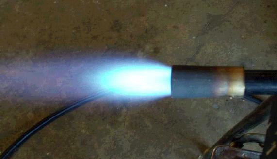
(Image courtesy of Don Foreman)
![]() Rupert Wenig has
provided
an excellent sequence of six
images of his Minimongo
Burner showing the effects on the burner flame of opening the choke. I
have
combined them into one image. The images on the right were taken
without
flash to show the flame characteristics more clearly. This is a very
instructional image, and should be extremely useful when you are tuning
any
kind of burner, not just the Mongo or Minimongo. You want to achieve a
neutral
flame as shown in the center image. Note:
The coupling that
Rupert is using for his flared nozzle has been machined out to have a
1:12
internal rate of flare...it is not just a coupling. Being cast iron it
would
also melt in an actual forge or furnace application. This is for test
purposes
only. Use stainless steel.
Rupert Wenig has
provided
an excellent sequence of six
images of his Minimongo
Burner showing the effects on the burner flame of opening the choke. I
have
combined them into one image. The images on the right were taken
without
flash to show the flame characteristics more clearly. This is a very
instructional image, and should be extremely useful when you are tuning
any
kind of burner, not just the Mongo or Minimongo. You want to achieve a
neutral
flame as shown in the center image. Note:
The coupling that
Rupert is using for his flared nozzle has been machined out to have a
1:12
internal rate of flare...it is not just a coupling. Being cast iron it
would
also melt in an actual forge or furnace application. This is for test
purposes
only. Use stainless steel.
T-Rex Flame Image - Ideal Neutral Flame
Side-arm Burner Flame Using Temporary Cast Iron Test Nozzle - Slightly Reducing Flame
Don's Flame Image - Oxidizing Flame
![]() Note about burner
nozzle placement in the forge:
Your burner nozzle should not enter the innermost layer of Kaowool. To
do
so will cause the nozzle to overheat and quickly degrade, or melt all
together.
Using a sharp knife, cut an "X" through both layers of Kaowool in front
of
the burner port, and from the outside, force the burner nozzle into the
forge
while spreading the Kaowool with your fingers to allow the nozzle to
squeeze
in. Stop when your have fully penetrated the outer layer of Kaowool.
Use
some kind of tapered plug, I use a turned hardwood plug, and from the
inside
of the chamber, force it through the X into the burner nozzle while
working
the Kaowool with your fingers to allow the plug to seat home against
and
inside the inner lip of the nozzle. The plug will need to have a
steeper
taper than the 1:12 that is inside the nozzle. By leaving the plug in
place
when the forge is not in use, it will force the Kaowool to take a set,
and
soon the plug will no longer be necessary. The hole in the inner layer
of
Kaowool will continue the tapering opening of the nozzle, and the 1"
setback
from the chamber will prevent the nozzle from being destroyed
prematurely.
Note about burner
nozzle placement in the forge:
Your burner nozzle should not enter the innermost layer of Kaowool. To
do
so will cause the nozzle to overheat and quickly degrade, or melt all
together.
Using a sharp knife, cut an "X" through both layers of Kaowool in front
of
the burner port, and from the outside, force the burner nozzle into the
forge
while spreading the Kaowool with your fingers to allow the nozzle to
squeeze
in. Stop when your have fully penetrated the outer layer of Kaowool.
Use
some kind of tapered plug, I use a turned hardwood plug, and from the
inside
of the chamber, force it through the X into the burner nozzle while
working
the Kaowool with your fingers to allow the plug to seat home against
and
inside the inner lip of the nozzle. The plug will need to have a
steeper
taper than the 1:12 that is inside the nozzle. By leaving the plug in
place
when the forge is not in use, it will force the Kaowool to take a set,
and
soon the plug will no longer be necessary. The hole in the inner layer
of
Kaowool will continue the tapering opening of the nozzle, and the 1"
setback
from the chamber will prevent the nozzle from being destroyed
prematurely.
The 2-1/2" Diameter Mongo Burner
The Mongo Burner
Series:
Mongo
Burner = 2-1/2" diameter
burner tube (Air starved)
Minimongo Burner
= 1-1/4" diameter
burner tube
Micromongo Burner
= 3/4" diameter burner
tube
Nanomongo Burner
= 1/2" diameter burner
tube
![]() Safety Warnings &
Considerations....a Must
Read:
The Side-arm burner
has now been perfected and can be found at the bottom of this section. You
are building and using this burner entirely at your own risk.
If you
don't wear eye protection, and you loose your eyesight due to the UV
radiation
that these burners can produce, then you are responsible for not
reading
and following the warnings, and must bear all consequences. I will not
accept
any liability for the stupidity of the builder and user of this device
if
he should injure himself with it by ignoring this warning. Please read
the
following e-mail I received. It will give you an idea of
the temperatures
these burners can achieve.
Safety Warnings &
Considerations....a Must
Read:
The Side-arm burner
has now been perfected and can be found at the bottom of this section. You
are building and using this burner entirely at your own risk.
If you
don't wear eye protection, and you loose your eyesight due to the UV
radiation
that these burners can produce, then you are responsible for not
reading
and following the warnings, and must bear all consequences. I will not
accept
any liability for the stupidity of the builder and user of this device
if
he should injure himself with it by ignoring this warning. Please read
the
following e-mail I received. It will give you an idea of
the temperatures
these burners can achieve.
"At this point, my only observation is that the (Micromongo) burner is too hot for the current nozzle design. Don't get me wrong, the burners worked great. I could not get the burners to run quite right without Larry Zoeller's nozzles, but I did not try very long, as I had a job that I had to get done this weekend ( I was already behind because I could not get enough heat out of the Reil Burner ). After going down to the welding store to buy a shaded full face plate (a definite necessity), I got right to work. Things were going great until the burners went erratic. The problem was that the nozzles got yellow+++ hot and sagged over the end of the burner. The nozzles now look like a tuba run over by a semi. I can not wait to get some more nozzles from Mr. Zoeller so I can form up some type of ceramic nozzle and start experimenting with this burner. Great potential. Thx's for all the help. Fred jyblood@nwi.net"
![]() There are a few more
items to address. It is apparent
in our testing that these burners display a very wide range of
behaviors
depending on what jet diameter is employed. Also, we are now using the
long
tapering copper 14T Tweco tips
for our jets,
even on the Reil and EZ-Burners, which I strongly recommend you do also
due
to the greatly increased performance they afford. I suggest you
experiment
with various diameter orifice Tweco tips and settle on one that works
best
for your particular application. See the FAQ for a listing of
nominal
to actual orifice diameters for these tips. They are threaded, 1/4"x 28
thread,
so you can easily switch them for experimentation. I may post a
"recommended
jet diameter" later on for each burner size, but presently I want to
leave
it open ended, even though the Mongo and Minimongo Burners both have
jets
called off in the information below which will provide a good starting
point
for you. Additionally, the tapered nozzle stainless steel flare
operates
at a much higher temperature, a red heat, on the Micromongo Burner than
on
the Reil or EZ Burners. This increased temperature will cause much more
rapid
degradation of the burner flare, even if its made of stainless steel.
In fact I would say that stainless
steel is your best option
for metal nozzles, and even their life may be fairly short, although
proper
mounting of the nozzle 1" back into the Kaowool will greatly extend its
life. I am getting more than three years out of a nozzle
presently. You
may want to consider casting your nozzle flare into the wall of your
rammable
refractory shell, if you have this kind of forge lining, thus
eliminating
the metal nozzle all together. This would be an easy task to perform,
and
may be the very best alternative for these high temperature burners.
Another
possibility is coating the nozzle, either stainless or black iron, with
ITC # 213. Have fun
and be careful!
There are a few more
items to address. It is apparent
in our testing that these burners display a very wide range of
behaviors
depending on what jet diameter is employed. Also, we are now using the
long
tapering copper 14T Tweco tips
for our jets,
even on the Reil and EZ-Burners, which I strongly recommend you do also
due
to the greatly increased performance they afford. I suggest you
experiment
with various diameter orifice Tweco tips and settle on one that works
best
for your particular application. See the FAQ for a listing of
nominal
to actual orifice diameters for these tips. They are threaded, 1/4"x 28
thread,
so you can easily switch them for experimentation. I may post a
"recommended
jet diameter" later on for each burner size, but presently I want to
leave
it open ended, even though the Mongo and Minimongo Burners both have
jets
called off in the information below which will provide a good starting
point
for you. Additionally, the tapered nozzle stainless steel flare
operates
at a much higher temperature, a red heat, on the Micromongo Burner than
on
the Reil or EZ Burners. This increased temperature will cause much more
rapid
degradation of the burner flare, even if its made of stainless steel.
In fact I would say that stainless
steel is your best option
for metal nozzles, and even their life may be fairly short, although
proper
mounting of the nozzle 1" back into the Kaowool will greatly extend its
life. I am getting more than three years out of a nozzle
presently. You
may want to consider casting your nozzle flare into the wall of your
rammable
refractory shell, if you have this kind of forge lining, thus
eliminating
the metal nozzle all together. This would be an easy task to perform,
and
may be the very best alternative for these high temperature burners.
Another
possibility is coating the nozzle, either stainless or black iron, with
ITC # 213. Have fun
and be careful!
![]() A
Note about Economy vs. Efficiency: There
are numerous
comments in my pages about "economy" and "efficiency." They do not mean
the
same thing. As I use these terms, the economy of a
burner refers to
how much its going to cost you to run it. The efficiency
of a burner,
in the way its used in my pages, refers to how much
air it can draw
in due to the strength of the vacuum it creates in the intake
bell
or ports at a given gas pressure. There are only so many BTUs available
in
a pound of propane, and no matter what you do you can not get any more
than
that out. If two different designs of burners are both running with a
totally
neutral burn at 100% combustion, and maintaining two identical forge
chambers
at the same temperature, their economy will be
identical. The Micromongo
Burner can produce higher temperatures than the Reil Burner, but it
uses
more fuel to do this. If you lower the output of the Micromongo so that
the
temperature inside the forge chamber is the same as in an identical
forge
chamber heated with a Reil Burner, the fuel usage, or economy,
should
be the same. If they are not, then one or the other is not running at
optimal
tuning. So don't choose the Micromongo Burner because you think it will
save
you money, it won't. It will give you the ability
to get the same
economy as provided by the Reil Burner, but it will also allow you to
reach
higher temperatures than the Reil Burner can attain, but this will cost
you
more in fuel usage. There is just no free lunch. It
is likely that
overall you will spend more money on fuel with the Micromongo burner
because
you will probably want to use that extra heat range to run a hotter
forge.
You pay for what you get. Note: We were very
surprised by the results
of some recent side by side tests of the T-Rex and Reil burners. They
both
consumed about the same amount of fuel, yet the T-Rex was much hotter.
We
concluded that the mixing and fuel/air ratios in the T-Rex are
superior,
and provide a better burn, thus extracting more of the BTU heat value
from
the fuel than the Reil burner is capable of doing. The T-Rex is both
more
economical, and more efficient. It is more econimical because it can be
run
at a lower gas pressure, using less fuel, and obtain a comparable
temperature
in the chamber.
A
Note about Economy vs. Efficiency: There
are numerous
comments in my pages about "economy" and "efficiency." They do not mean
the
same thing. As I use these terms, the economy of a
burner refers to
how much its going to cost you to run it. The efficiency
of a burner,
in the way its used in my pages, refers to how much
air it can draw
in due to the strength of the vacuum it creates in the intake
bell
or ports at a given gas pressure. There are only so many BTUs available
in
a pound of propane, and no matter what you do you can not get any more
than
that out. If two different designs of burners are both running with a
totally
neutral burn at 100% combustion, and maintaining two identical forge
chambers
at the same temperature, their economy will be
identical. The Micromongo
Burner can produce higher temperatures than the Reil Burner, but it
uses
more fuel to do this. If you lower the output of the Micromongo so that
the
temperature inside the forge chamber is the same as in an identical
forge
chamber heated with a Reil Burner, the fuel usage, or economy,
should
be the same. If they are not, then one or the other is not running at
optimal
tuning. So don't choose the Micromongo Burner because you think it will
save
you money, it won't. It will give you the ability
to get the same
economy as provided by the Reil Burner, but it will also allow you to
reach
higher temperatures than the Reil Burner can attain, but this will cost
you
more in fuel usage. There is just no free lunch. It
is likely that
overall you will spend more money on fuel with the Micromongo burner
because
you will probably want to use that extra heat range to run a hotter
forge.
You pay for what you get. Note: We were very
surprised by the results
of some recent side by side tests of the T-Rex and Reil burners. They
both
consumed about the same amount of fuel, yet the T-Rex was much hotter.
We
concluded that the mixing and fuel/air ratios in the T-Rex are
superior,
and provide a better burn, thus extracting more of the BTU heat value
from
the fuel than the Reil burner is capable of doing. The T-Rex is both
more
economical, and more efficient. It is more econimical because it can be
run
at a lower gas pressure, using less fuel, and obtain a comparable
temperature
in the chamber.
![]() The only exception to
the basic statements above may be when using a Mongo Series
Burner, or
one of the big Rex series burners, to run a melting furnace. If you are
able
to achieve a higher temperature in the furnace with a bigger burner, it
will
achieve the melt more quickly, which cuts the time available for heat
to
escape through the furnace walls and up the stack, thus wasting fewer
BTUs.
However, the higher temperature creates a greater thermal gradient
across
the thickness of the furnace wall, increasing the amount of heat loss
in
a given time, so there is a trade-off to consider. If the Furnace walls
were
made of 100% efficient insulation this relationship would not exist,
and
the burners would perform with equal economy, but perhaps not
convenience.
I point out these various relationships to show you that things are not
as
simple as they may sometimes appear. There are a lot of factors to take
into
account when discussing economy of a burner. For the most part, the
smith
operating the forge, and the quality of the forge, will be the most
important
factors in determining overall economy, not the burner. Think about
running
your burner to do a day's forging, without the benefit of a forge
chamber,
and you will understand my last comment.
The only exception to
the basic statements above may be when using a Mongo Series
Burner, or
one of the big Rex series burners, to run a melting furnace. If you are
able
to achieve a higher temperature in the furnace with a bigger burner, it
will
achieve the melt more quickly, which cuts the time available for heat
to
escape through the furnace walls and up the stack, thus wasting fewer
BTUs.
However, the higher temperature creates a greater thermal gradient
across
the thickness of the furnace wall, increasing the amount of heat loss
in
a given time, so there is a trade-off to consider. If the Furnace walls
were
made of 100% efficient insulation this relationship would not exist,
and
the burners would perform with equal economy, but perhaps not
convenience.
I point out these various relationships to show you that things are not
as
simple as they may sometimes appear. There are a lot of factors to take
into
account when discussing economy of a burner. For the most part, the
smith
operating the forge, and the quality of the forge, will be the most
important
factors in determining overall economy, not the burner. Think about
running
your burner to do a day's forging, without the benefit of a forge
chamber,
and you will understand my last comment.
The Mongo Burner & New Side-arm Burner
Note: For historical purposes, and to keep information available that may be of use to someone, I have not removed the drilled air intake hole Mongo burners from this page, nor the old Side-arm information shown several paragraphs below. The drilled hole ports are too small to provide the necessary intake air volume on the original Mongo burner, resulting in a very rich burn and high CO production...potentially dangerous. The original Side-arm burner design has also proven to be an inferior design if built as shown in this drawing, and I do not recommend it. There is now a far superior option available which turns the Side-arm burner into to a very fine burner by using an asymmetric T-fitting. If you enlarge the "intake" bell opening, as shown in the images linked a couple sentences below, the inlet "R" value will drop to a level to allow these burners to perform extremely well, especially if you use a Tweco 14T jet tip. Larry Zoeller has been experimenting with this concept and has provided some examples of high quality Side-arm burners. Check these out if you want a good example of these very easily and quickly made burners. Paul Pirtle has also been working on these burners and has produced an excellent Side-arm burner, shown with "axial" choke installed, which performs extremely well across the entire pressure range. He has since replaced the cast iron test nozzle with a stainless steel nozzle so that it will not melt in his forge chamber. Please do not use cast iron. The following are a few comments Paul sent me regarding his excellent Side-arm burner. I include it here because the jet orifice information may be of use to you.
"Yesterday I built two air choke assemblies, using a 1-1/4" short nipple with round choke plate, 1/4-20 all-thread, and a brazed T per your design. Tested both, they work perfectly to adjust flame to blue/green transition. Based on how far the choke needed to be closed I think I could run a larger than .035" orifice. I tested the .023 orifice again with choke, it runs fine but fussier than the .035. I am guessing it might be marginal to small for the 3/4" burner tube. A 1-1/4"x 1-1/4" x 3/4" cast iron T-fitting is necessary to provide the needed intake air flow volume for a 3/4" burner." (It may be possible to use a smaller bell on the top end of the fitting where the jet pipe enters, perhaps a 1" x 1-1/4" x 3/4" or even a 3/4" x 1-1/4" x 3/4" fitting.)
![]() The original Mongo
burner
is a huge multi-purpose "Jet Ejector" burner. I was so impressed after
I
built one, even though it had a too short burner tube and no nozzle,
that
I felt it deserved a place on this page. I named it after "Mongo," the
giant
in "Blazing Saddles," because of its huge size.... 2-1/2" diameter
bore!
It is a different design of burner, having seven 1" diameter air holes
in
the barrel of the burner, and an axial 1/2" diameter internal jet tube,
but
it works quite well, except for not being able to get a fully balanced
fuel/air
mixture. It tends to run on the fuel rich side due to the small intake
port
area and resulting insufficient intake air volume. When I first tried
test
firing it I was unable to run it below 20 psi or it would become
erratic
and run extremely rough. I switched out the jet tube for one 1" longer,
to
get the jet just slightly downstream of the air intake openings. This
made
a huge difference. I can now run the pressure down to zero gage
pressure,
doesn't show on my gage at all, but it is probably about 1/10 psi, and
it
purrs away just beautifully at a very reduced output. This low end
operating
range is due to the 28:1 induction ratio of jet ejector burners, as
compared
with the 20:1 ratio for the linear inducer burner like the "Reil or EZ
Burners."
This burner has tremendous adjustability in its output, making it
useful
for kilns, but the possible CO dangers need to be considered and
precautions
taken. For forge use, I strongly recommend going to an asymetric
Side-arm
design as shown at the top of this
section, and use
of a flared nozzle.
The original Mongo
burner
is a huge multi-purpose "Jet Ejector" burner. I was so impressed after
I
built one, even though it had a too short burner tube and no nozzle,
that
I felt it deserved a place on this page. I named it after "Mongo," the
giant
in "Blazing Saddles," because of its huge size.... 2-1/2" diameter
bore!
It is a different design of burner, having seven 1" diameter air holes
in
the barrel of the burner, and an axial 1/2" diameter internal jet tube,
but
it works quite well, except for not being able to get a fully balanced
fuel/air
mixture. It tends to run on the fuel rich side due to the small intake
port
area and resulting insufficient intake air volume. When I first tried
test
firing it I was unable to run it below 20 psi or it would become
erratic
and run extremely rough. I switched out the jet tube for one 1" longer,
to
get the jet just slightly downstream of the air intake openings. This
made
a huge difference. I can now run the pressure down to zero gage
pressure,
doesn't show on my gage at all, but it is probably about 1/10 psi, and
it
purrs away just beautifully at a very reduced output. This low end
operating
range is due to the 28:1 induction ratio of jet ejector burners, as
compared
with the 20:1 ratio for the linear inducer burner like the "Reil or EZ
Burners."
This burner has tremendous adjustability in its output, making it
useful
for kilns, but the possible CO dangers need to be considered and
precautions
taken. For forge use, I strongly recommend going to an asymetric
Side-arm
design as shown at the top of this
section, and use
of a flared nozzle.
![]() The original
Mongo burner
design discussed in the paragraph above was sent to me by Richard Mize,
in
Kentucky, and I have to thank him very much for sharing it with us. He
included
some additional information and suggestions in his drawings which I too
included
in the packet of drawings. I did not build the refractory venturi
throat,
nor the bracket he suggests, at least not yet. I have simply run scans
of
Richard's hand drawings and posted them below
for
download. It is a zipped file containing 6 images, including an
assembly
drawing, text comment sheets, refractory venturi throat, mounting
bracket,
mounting suggestions, and a list of materials needed. I have reduced
them
in size to allow downloading to be faster, but all together they are
still
264K in size. These are hand drawings with hand written notes. They
were
plenty good enough for me to produce a dandy burner, and I am sure they
will
work just as well for you. An alternative that I strongly recommend due
to
its small file size is the "pdf" Adobe Acrobat file I have
available
also. This is a single fine quality drawing, with fewer notes and
comments,
and it is a much smaller file. It should be plenty detailed to allow
you
to build the burner without problem. Click on the gif "preview file" to
see
a reduced size image of the "pdf" construction file. The preview image
may
be all you will need to build this burner, but the text is
pretty small
for older eyes like mine. I do want to say that I strongly suggest the
Side-arm
burner discussed above, which is easier to build and produces a fully
balanced
fuel/air ratio, and no CO danger if adjusted correctly.
The original
Mongo burner
design discussed in the paragraph above was sent to me by Richard Mize,
in
Kentucky, and I have to thank him very much for sharing it with us. He
included
some additional information and suggestions in his drawings which I too
included
in the packet of drawings. I did not build the refractory venturi
throat,
nor the bracket he suggests, at least not yet. I have simply run scans
of
Richard's hand drawings and posted them below
for
download. It is a zipped file containing 6 images, including an
assembly
drawing, text comment sheets, refractory venturi throat, mounting
bracket,
mounting suggestions, and a list of materials needed. I have reduced
them
in size to allow downloading to be faster, but all together they are
still
264K in size. These are hand drawings with hand written notes. They
were
plenty good enough for me to produce a dandy burner, and I am sure they
will
work just as well for you. An alternative that I strongly recommend due
to
its small file size is the "pdf" Adobe Acrobat file I have
available
also. This is a single fine quality drawing, with fewer notes and
comments,
and it is a much smaller file. It should be plenty detailed to allow
you
to build the burner without problem. Click on the gif "preview file" to
see
a reduced size image of the "pdf" construction file. The preview image
may
be all you will need to build this burner, but the text is
pretty small
for older eyes like mine. I do want to say that I strongly suggest the
Side-arm
burner discussed above, which is easier to build and produces a fully
balanced
fuel/air ratio, and no CO danger if adjusted correctly.
![]() Alternate Side-arm
Design:
(Note: this is older information, but is preserved for its historical
value.
Please see the latest Side-arm information at the top
of this section.) You can build this burner more easily if
you substitute
a large "T" fitting, see link, in place of the pipe coupling.
The burner
tube screws into one arm of the "T", and the reducer and jet tube into
the
other arm. The air intake is provided by the opening in the base of the
"T"
fitting. You will not need to drill the big air intake holes this way.
Also,
it can be easily choked using a butterfly choke design, or an axial
choke
design, which is placed in the "foot" of the "T". You will have to
experiment
to determine the proper length of axial jet tube in order to place the
jet
in the right location in relation to the incoming air. I have not tried
these
modifications to the burner design. (Thanks goes to "Frosty"
in Alaska
for this suggestion, and the induction ratio information above.)
Robert Grauman
has built one
he has named the "Side-arm Design,"
in the Minimongo
diameter, and this is what he has to say. (Note: I strongly recommend
using
a 1/8" jet tube, instead of the 1/4" tube shown in the
drawing.) "I used to have a choke plate in
the air tube, but I
found I was getting a neutral burn with the choke wide open, so I
removed
the choke, and am now running with the inlet wide open. This has
simplified
the burner considerably. I am using a #55 (0.052") jet at about 22 psi.
The
flame burns near neutral (I think), but it requires a flame holder on
the
end of the burner tube when the burner is not in the burner port of my
crucible furnace. It burns quietly. If provoked, the
flame will burn
back in the burner tube, but I believe that the burner tube is too
long.
I will start experimenting in that area tomorrow. The burner seems to
work
best with the jet cantered on the air tube, but it is non-critical."
Alternate Side-arm
Design:
(Note: this is older information, but is preserved for its historical
value.
Please see the latest Side-arm information at the top
of this section.) You can build this burner more easily if
you substitute
a large "T" fitting, see link, in place of the pipe coupling.
The burner
tube screws into one arm of the "T", and the reducer and jet tube into
the
other arm. The air intake is provided by the opening in the base of the
"T"
fitting. You will not need to drill the big air intake holes this way.
Also,
it can be easily choked using a butterfly choke design, or an axial
choke
design, which is placed in the "foot" of the "T". You will have to
experiment
to determine the proper length of axial jet tube in order to place the
jet
in the right location in relation to the incoming air. I have not tried
these
modifications to the burner design. (Thanks goes to "Frosty"
in Alaska
for this suggestion, and the induction ratio information above.)
Robert Grauman
has built one
he has named the "Side-arm Design,"
in the Minimongo
diameter, and this is what he has to say. (Note: I strongly recommend
using
a 1/8" jet tube, instead of the 1/4" tube shown in the
drawing.) "I used to have a choke plate in
the air tube, but I
found I was getting a neutral burn with the choke wide open, so I
removed
the choke, and am now running with the inlet wide open. This has
simplified
the burner considerably. I am using a #55 (0.052") jet at about 22 psi.
The
flame burns near neutral (I think), but it requires a flame holder on
the
end of the burner tube when the burner is not in the burner port of my
crucible furnace. It burns quietly. If provoked, the
flame will burn
back in the burner tube, but I believe that the burner tube is too
long.
I will start experimenting in that area tomorrow. The burner seems to
work
best with the jet cantered on the air tube, but it is non-critical."
![]() Please note that
Robert
uses the burner in a cast iron and aluminum melting furnace, not a
forge.
You will want to operate at much lower pressures for forge work. Note:
From tests done by Michael, it appears the "Sidearm" design is not a
good
choice for the smaller Micromongo and Nanomongo burners. He was unable
to
achieve a stable flame over a range of gas pressures in his Sidearm
Micromongo
test burner.
Please note that
Robert
uses the burner in a cast iron and aluminum melting furnace, not a
forge.
You will want to operate at much lower pressures for forge work. Note:
From tests done by Michael, it appears the "Sidearm" design is not a
good
choice for the smaller Micromongo and Nanomongo burners. He was unable
to
achieve a stable flame over a range of gas pressures in his Sidearm
Micromongo
test burner.
![]() Note:
There is one important
error in the Adobe Acrobat "pdf" file below. The jet opening should
read
"#52 = 0.0625" diameter", not #58. This is a very
important
difference.
Note:
There is one important
error in the Adobe Acrobat "pdf" file below. The jet opening should
read
"#52 = 0.0625" diameter", not #58. This is a very
important
difference.
Preview the Following "pdf" file as a Reduced Size "gif" Image
Download a Single Complete Design File in "pdf" Format (Recommended - 16K)
Download all Six Construction Drawings in Zipped "gif" Format (264K)
(Before considering the construction of any of the Mongo series of burners, please read the informationa about the Side-arm burners at the top of this section.)
![]() If you don't have
"Adobe
Acrobat Reader" on your computer you may
download
it
here, its free.
If you don't have
"Adobe
Acrobat Reader" on your computer you may
download
it
here, its free.
![]() "Minimongo
Burner":
I received a communication
from Rupert Wenig
regarding a
half scale version of the
Mongo Burner that he is
using to fire his cast iron melting furnace. His experimentation work
is
continuing, but here are his latest design modification details. He is
getting
good results with it using these parameters. See the cast iron test
melt
results below the following specs Rupert provided. For forge use, I
strongly
recommend going to an asymetric Side-arm design as shown at the
top of this section, and use
of a flared nozzle.
"Minimongo
Burner":
I received a communication
from Rupert Wenig
regarding a
half scale version of the
Mongo Burner that he is
using to fire his cast iron melting furnace. His experimentation work
is
continuing, but here are his latest design modification details. He is
getting
good results with it using these parameters. See the cast iron test
melt
results below the following specs Rupert provided. For forge use, I
strongly
recommend going to an asymetric Side-arm design as shown at the
top of this section, and use
of a flared nozzle.
-Burner tube: black iron pipe,
1-1/4" diameter by 12" long
-Jet: #56 drill = 0.0465"diameter (You may need to experiment further
to
determine the optimum jet opening)
-Air induction holes: 13/16" diameter
-Additional changes in Rupert's own words: "I
also changed the
pipe bushing to a standard easier to get one. As pipe bushings are not
normally
solid I made a plug to fit the inside of the bushing to give the fuel
pipe
more surface area to hold it straight. I then drilled a clearance hole
through
the plug and bushing and installed a set screw to clamp the fuel pipe
in
place. This allowed adjusting the position of the fuel jet. Another
change
I made for convenience was to thread the inside of the fuel pipe so
that
I could use the jets I had on hand."
"PS. There is no
question that this burner is quieter than other burners I have
tried."
![]() Rupert's
Cast Iron
Melt Results Using the Minimongo Burner Without Flared
Nozzle:
Rupert's
Cast Iron
Melt Results Using the Minimongo Burner Without Flared
Nozzle:
I did a cast iron melt with the Minimongo today. I
ran the furnace
for 1:12 hrs, melting 15# of cast iron while running the burner at 20
psi
after a 2 min. warm up from a cold start-up. That equates to about 0.21
lb/min.
From my logs the Monster burner melted 17 lb. in 1:13 hrs. This equates
to
0.23 lb./min.
Unfortunately, the casting didn't turn out because I got impatient. I should have superheated the melt for another 2 or 3 min as the casting I poured was a very thin section (1/4"). I would say that this compares favorably (with the Monster burner) as the Minimongo has a #56 jet in it while the Monster burner had a #54 jet.
![]() Based on the
latest
information I am receiving, you will need to make a 1:12 tapered nozzle
flare,
for the Minimongo burner, and probably for the Mongo Burner as well,
once
it has been fully tuned.
Based on the
latest
information I am receiving, you will need to make a 1:12 tapered nozzle
flare,
for the Minimongo burner, and probably for the Mongo Burner as well,
once
it has been fully tuned.
![]() Thanks to the work
of
Robert Grauman
in "Sunny Alberta,"
we now have a very fine jpg drawing of the "Minimongo Burner" that
Rupert
has provided information for. You may click the link below to view the
design
drawing. This drawing incorporates all of Rupert's modifications to the
full
scale version, including some details he did not mention above. Thanks
Robert.
Thanks to the work
of
Robert Grauman
in "Sunny Alberta,"
we now have a very fine jpg drawing of the "Minimongo Burner" that
Rupert
has provided information for. You may click the link below to view the
design
drawing. This drawing incorporates all of Rupert's modifications to the
full
scale version, including some details he did not mention above. Thanks
Robert.
Mongo
Burner Half Scale Design
Drawing
Note: I strongly recommend using
a 1/8" jet tube, instead
of the 1/4" tube shown in the drawing.
![]() Choke
Settings
Image: The below linked image is a
composite image of six
images Rupert sent me of his Minimongo Burner, photographed at three
different
choke settings, rich, neutral, and lean. All the images were shot at a
gas
pressure setting of 10 psi. The images on the right were taken without
flash
to show the flame characteristics more clearly. This is a long needed
set
of images that are very helpful when attempting to tune any kind of
burner
for a neutral burn, not just the Mongo or Minimongo Burners. Note:
The coupling that Rupert is using for his flared nozzle has been
machined
out to have a 1:12 internal rate of flare...it is not just a coupling.
Choke
Settings
Image: The below linked image is a
composite image of six
images Rupert sent me of his Minimongo Burner, photographed at three
different
choke settings, rich, neutral, and lean. All the images were shot at a
gas
pressure setting of 10 psi. The images on the right were taken without
flash
to show the flame characteristics more clearly. This is a long needed
set
of images that are very helpful when attempting to tune any kind of
burner
for a neutral burn, not just the Mongo or Minimongo Burners. Note:
The coupling that Rupert is using for his flared nozzle has been
machined
out to have a 1:12 internal rate of flare...it is not just a coupling.
Minimongo Showing Flame Under Different Choke Settings at 10 psi Gas Pressure
(Be sure you also look at the full output image)
![]() Micromongo and Nanomongo
Burner
Designs: We
now have good Micromongo and Nanomongo
Burners in operation, and the development work is complete.
Michael has
performed virtually all
the development work for this burner, while communicating and
discussing
possible alterations and modifications with me. I credit these burners
to
his tireless hours of modification and development. For the Micromongo
Burner,
Michael suggests starting with a #65 jet diameter. This appears to be a
good
jet diameter in his test burner, but we may modify this recommendation
after
the burner undergoes an extended period of "on the job" testing.
Absolutely
do use the 14T
Tweco tips discussed above,
and the movable tunable jet pipe modification shown in the
Minimongo Burner design
images. (Note: I strongly
recommend using a 1/8" jet tube, instead of the 1/4" tube shown in the
drawing.)
Micromongo and Nanomongo
Burner
Designs: We
now have good Micromongo and Nanomongo
Burners in operation, and the development work is complete.
Michael has
performed virtually all
the development work for this burner, while communicating and
discussing
possible alterations and modifications with me. I credit these burners
to
his tireless hours of modification and development. For the Micromongo
Burner,
Michael suggests starting with a #65 jet diameter. This appears to be a
good
jet diameter in his test burner, but we may modify this recommendation
after
the burner undergoes an extended period of "on the job" testing.
Absolutely
do use the 14T
Tweco tips discussed above,
and the movable tunable jet pipe modification shown in the
Minimongo Burner design
images. (Note: I strongly
recommend using a 1/8" jet tube, instead of the 1/4" tube shown in the
drawing.)
![]() Nanomongo Burner:
I am posting an image
of the prototype
Nanomongo burner if you
are interested in where we are going with this design. Michael
came up with this version, and it has good operating characteristics.
The
burner is totally stable from zero psi gage (the needle was resting on
the
peg in both of my test jig gages), to 30 psi plus. In the
image the
burner is burning at a pressure of 10 psi, but due to the sunlight you
are
unable to detect any flame in the nozzle. The burner is 100% copper and
brass,
with a high chromium stainless steel nozzle. The
interior of the
nozzle is machined to a 1:12 taper, but it additionally has a "step" of
about
1/8" where it meets the end of the burner tube to increase the diameter
a
quarter inch, the same as the normal flared nozzle does on other
burners
due to the 1/8" thickness of the burner tube wall. We found this "step"
to
be necessary due to the thin wall of the copper pipe. It turns out the
"step"
is a critical part of the flare's operational design. We
have
determined that the secondary set of smaller air intake holes toward
the
rear of the burner are not necessary, and will not be included in the
next
version. The entire air intake assembly will be shortened and
simplified.
It will also include a sliding sleeve choke, although the present
version
displays an apparently neutral burn across its entire operating range,
at
least as much as I can determine at this point. The four screws in the
forward
part of the intake are to precisely align the jet, and will be moved
toward
the rear and reduced to three in number in the next version. The jet
orifice
is a 0.023" diameter, 0.60 mm, Tweco tip, silver soldered on
the end
of a 1/8" brass jet tube. There is also a set screw in the back of the
rear
of the burner to lock the jet tube from forward or backward movement.
Nanomongo Burner:
I am posting an image
of the prototype
Nanomongo burner if you
are interested in where we are going with this design. Michael
came up with this version, and it has good operating characteristics.
The
burner is totally stable from zero psi gage (the needle was resting on
the
peg in both of my test jig gages), to 30 psi plus. In the
image the
burner is burning at a pressure of 10 psi, but due to the sunlight you
are
unable to detect any flame in the nozzle. The burner is 100% copper and
brass,
with a high chromium stainless steel nozzle. The
interior of the
nozzle is machined to a 1:12 taper, but it additionally has a "step" of
about
1/8" where it meets the end of the burner tube to increase the diameter
a
quarter inch, the same as the normal flared nozzle does on other
burners
due to the 1/8" thickness of the burner tube wall. We found this "step"
to
be necessary due to the thin wall of the copper pipe. It turns out the
"step"
is a critical part of the flare's operational design. We
have
determined that the secondary set of smaller air intake holes toward
the
rear of the burner are not necessary, and will not be included in the
next
version. The entire air intake assembly will be shortened and
simplified.
It will also include a sliding sleeve choke, although the present
version
displays an apparently neutral burn across its entire operating range,
at
least as much as I can determine at this point. The four screws in the
forward
part of the intake are to precisely align the jet, and will be moved
toward
the rear and reduced to three in number in the next version. The jet
orifice
is a 0.023" diameter, 0.60 mm, Tweco tip, silver soldered on
the end
of a 1/8" brass jet tube. There is also a set screw in the back of the
rear
of the burner to lock the jet tube from forward or backward movement.
![]() Michael
determined that
this burner had to be modified with a larger intake diameter, in order
to
draw in the necessary quantity of air to balance the gas volume. The
burner
tube diameter is 1/2," and bells out to 1" in the intake chamber. This
burner
will easily match the Micromongo burner, 3/4" burner tube, in its
output.
It is very impressive, especially its flawlessly smooth operating range
of
zero psi to 30 psi plus. My test jig gages would not allow me to test
it
at pressures exceeding this level. As Michael mentioned to me, in the
upper
pressure range you can actually feel the air suction with your hand at
a
distance of 8" from the burner! The venturi
vacuum is very
impressive.
Michael
determined that
this burner had to be modified with a larger intake diameter, in order
to
draw in the necessary quantity of air to balance the gas volume. The
burner
tube diameter is 1/2," and bells out to 1" in the intake chamber. This
burner
will easily match the Micromongo burner, 3/4" burner tube, in its
output.
It is very impressive, especially its flawlessly smooth operating range
of
zero psi to 30 psi plus. My test jig gages would not allow me to test
it
at pressures exceeding this level. As Michael mentioned to me, in the
upper
pressure range you can actually feel the air suction with your hand at
a
distance of 8" from the burner! The venturi
vacuum is very
impressive.
![]() My Personal Observations:
I have finally had
the opportunity to try out one of the Micromongo burners in a short but
interesting test. It is a reasonably good burner. I experimented with
the
nozzle flare adjustment to achieve the lowest input pressure, while
maintaining
a stable flame, and the results were better than I had hoped. With only
3/4"
of flare exposure, the burner was stable to pressures down to 1 psi, or
even
a little lower. I did not have my most accurate gage on the system, so
I
am not sure exactly how low it went, but the gage needle was almost
riding
on the peg. This was after only about 15 minutes of experimentation.
There
is a very critical interaction between the jet location, centering, and
the
flare location, and the jet tube was loose in the mounting so I was
unable
to perfect the adjustment to its finest degree. I think that it is
entirely
possible to get this burner to operate in a stable manor at gas
pressures
down into the ounces range. Its upper end range is a given, but the low
end
capability makes it a very special burner indeed. This low end
operation
range is of no consequence when the burner is used in a melting
furnace,
but in a forge the low end ability will be extremely useful for some
operations.
It is possible that when I switch the present jet to one that is larger
it
will change this low end performance. That is yet to be determined.
Parts
breakdown image for the
Micromongo (Before
considering the construction of
any of the Mongo series of burners, please read the information about
the
Side-arm burners at the top of this
section.)
My Personal Observations:
I have finally had
the opportunity to try out one of the Micromongo burners in a short but
interesting test. It is a reasonably good burner. I experimented with
the
nozzle flare adjustment to achieve the lowest input pressure, while
maintaining
a stable flame, and the results were better than I had hoped. With only
3/4"
of flare exposure, the burner was stable to pressures down to 1 psi, or
even
a little lower. I did not have my most accurate gage on the system, so
I
am not sure exactly how low it went, but the gage needle was almost
riding
on the peg. This was after only about 15 minutes of experimentation.
There
is a very critical interaction between the jet location, centering, and
the
flare location, and the jet tube was loose in the mounting so I was
unable
to perfect the adjustment to its finest degree. I think that it is
entirely
possible to get this burner to operate in a stable manor at gas
pressures
down into the ounces range. Its upper end range is a given, but the low
end
capability makes it a very special burner indeed. This low end
operation
range is of no consequence when the burner is used in a melting
furnace,
but in a forge the low end ability will be extremely useful for some
operations.
It is possible that when I switch the present jet to one that is larger
it
will change this low end performance. That is yet to be determined.
Parts
breakdown image for the
Micromongo (Before
considering the construction of
any of the Mongo series of burners, please read the information about
the
Side-arm burners at the top of this
section.)
*** Rules Of Thumb for Forge Design ***
(For
the 3/4" diameter Reil or EZ burners
only)
*Do not use these rules for the Mongo series of burners*
![]() If you want to
design
your own gas forge there are a few simple "rules of thumb" to
keep in
mind. These are not exact, and may not even result in a successful
forge,
but they are a starting place for designing your own propane forge
system.
There are a great many variables involved with any forge system,
insulation
"R" value, exhaust opening area, smoothness of burner penetrations,
elevation,
quality of forge and burner construction, jet diameter, tuning, etc.,
to
name but a few. Any one of them can cause problems. To design forges
using
other burner types, use the BTU Calculator,
along with
the information in paragraph #1 below.**
If you want to
design
your own gas forge there are a few simple "rules of thumb" to
keep in
mind. These are not exact, and may not even result in a successful
forge,
but they are a starting place for designing your own propane forge
system.
There are a great many variables involved with any forge system,
insulation
"R" value, exhaust opening area, smoothness of burner penetrations,
elevation,
quality of forge and burner construction, jet diameter, tuning, etc.,
to
name but a few. Any one of them can cause problems. To design forges
using
other burner types, use the BTU Calculator,
along with
the information in paragraph #1 below.**
1. You will need at least 450 BTUs per cubic inch of forge chamber volume if your forge is going to be able to forge-weld. Some would argue for a figure as high as 540 BTUs per cubic inch.
2. The "Reil Burner" will deliver about 135,000 BTUs at medium to higher gas pressures, and can be cranked up to almost 200,000 BTUs by raising the pressure to 20 psi or more. In the lower pressure range of from 1-6 psi, where I do most of my work, it will produce about 60,000 BTUs, or even a little less. Use the middle figure in any design calculations.
3. Shoot for a burner to volume ratio of 1:300 or less. Some smiths who are very knowledgeable would say a more conservative ratio of 1:250 would be safer and insure that your forge will be able to weld. To calculate how many 3/4" burners you will need just divide the total chamber volume of your forge, in cubic inches, by 250 or 300, and then round up. If you come out to a burner requirement of 2-1/3 burners, then you will need 3 burners for your planned forge volume. Always plan conservatively or you may end up with a forge that is too cold to forge-weld.**
![]() It should be
apparent
that a 4' long by 2' diameter pipe forge will require far too
many 3/4"
burners to be practical. Keep your forge chamber as small as possible.
If
you can't build what you need with these burners you may need to look
at
the "Monster-Burner" as a
possible alternative to
heat your forge. I will not provide rules of thumb for them, so please
don't
ask. You can easily enough get a "propane jet diameter/BTU output
table"
and figure this information out yourself. These tables are available
locally
through your propane dealer or on the Net.
It should be
apparent
that a 4' long by 2' diameter pipe forge will require far too
many 3/4"
burners to be practical. Keep your forge chamber as small as possible.
If
you can't build what you need with these burners you may need to look
at
the "Monster-Burner" as a
possible alternative to
heat your forge. I will not provide rules of thumb for them, so please
don't
ask. You can easily enough get a "propane jet diameter/BTU output
table"
and figure this information out yourself. These tables are available
locally
through your propane dealer or on the Net.
** The above information is assuming that you will build a well insulated forge, having at least 2" of Kaowool lining coated with ITC-100, not Satinite, on the interior surface of the chamber. A 3" lining of Kaowool would be even better, and would probably pay for itself in fuel savings over the long run. If you elect to use a rammable or pourable refractory, or bricks, you will have to address the lower insulation values associated with these materials. One option is a composite design, a pourable refractory shell for durability, inside a Kaowool shell for insulation value. These are more difficult to build but are long lasting and can work very well.

23 Nov 07
©Golden Age Forge
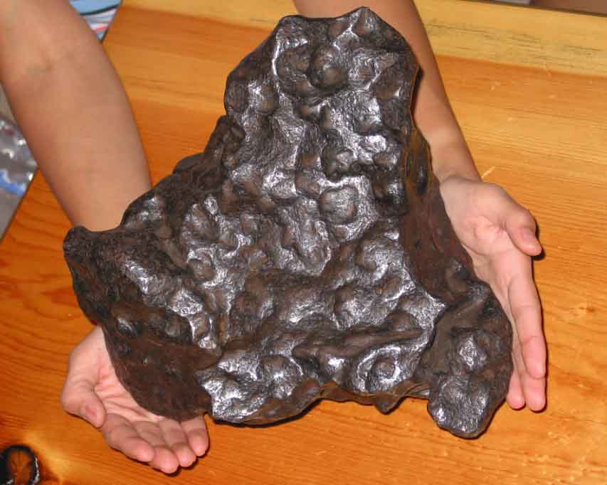
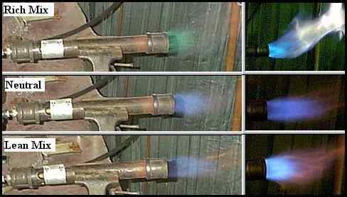
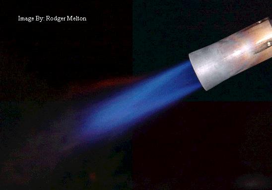
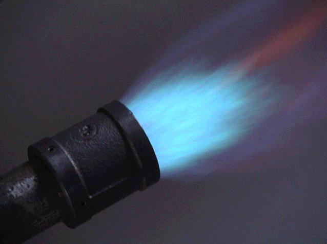
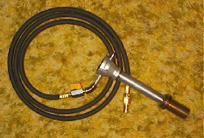
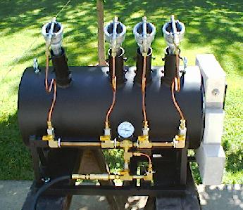
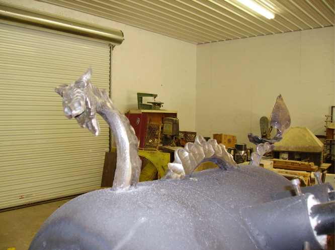
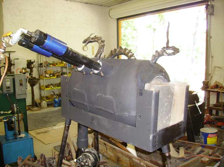
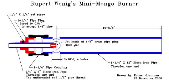
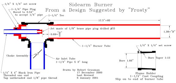
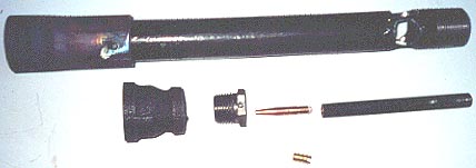