
Ron's Fly-Press Page
Contact me by phone: (208) 462-4028
Note: Due to spam problems I no longer post my e-mail address.
Note: I have nothing for sale on this page or Web site.
Forward
![]() This page is dedicated
to setting up and working an historic forging tool which greatly
predates
the hydraulic press, the "fly-press."
This
tool is rarely found in western US smithies, but is a very common tool in
hot-shops
in Europe. I am providing this page as a source of information for
those
of you who, like me, have obtained one for their shop, and discovered
that
there is very little information out there regarding setting up and
using
one of these wonderful machines. I have a #P-6 fly-press that weighs
roughly
700 pounds, and a #P-0. Getting the P-6 shipped to my shop, moving it into the shop,
building
its mobile fly-press stand,
and getting it lifted
on to the stand, has been quite a task. I will attempt to highlight
the most important aspects of this adventure in setting up my first fly-press.
This page is dedicated
to setting up and working an historic forging tool which greatly
predates
the hydraulic press, the "fly-press."
This
tool is rarely found in western US smithies, but is a very common tool in
hot-shops
in Europe. I am providing this page as a source of information for
those
of you who, like me, have obtained one for their shop, and discovered
that
there is very little information out there regarding setting up and
using
one of these wonderful machines. I have a #P-6 fly-press that weighs
roughly
700 pounds, and a #P-0. Getting the P-6 shipped to my shop, moving it into the shop,
building
its mobile fly-press stand,
and getting it lifted
on to the stand, has been quite a task. I will attempt to highlight
the most important aspects of this adventure in setting up my first fly-press.
![]() First, you might wonder
what a fly-press is. It is a manually operated screw press which has a
massive
screw and flywheel, or ball weighted handle, attached to the
top of
the screw to provide inertia to drive the screw down, which pushes the
ram
block/tool holder on to the work. It creates a tremendous force, and
allows
the operator to bend, forge, pierce, punch, or texture, metals
precisely
and easily once the necessary tooling has been made. Additionally, it
provides
tactile feedback to the operator, allowing very delicate work to be
done
that is pretty much beyond the range of hydraulic presses. Further, it
only
places the tool in contact with the work momentarily,
preserving the
heat in the work much more effectively than hydraulic presses. Besides,
it
is clean, uses no messy hydraulic oil, has no smell, requires no power
supply,
and it just works really well.
First, you might wonder
what a fly-press is. It is a manually operated screw press which has a
massive
screw and flywheel, or ball weighted handle, attached to the
top of
the screw to provide inertia to drive the screw down, which pushes the
ram
block/tool holder on to the work. It creates a tremendous force, and
allows
the operator to bend, forge, pierce, punch, or texture, metals
precisely
and easily once the necessary tooling has been made. Additionally, it
provides
tactile feedback to the operator, allowing very delicate work to be
done
that is pretty much beyond the range of hydraulic presses. Further, it
only
places the tool in contact with the work momentarily,
preserving the
heat in the work much more effectively than hydraulic presses. Besides,
it
is clean, uses no messy hydraulic oil, has no smell, requires no power
supply,
and it just works really well.
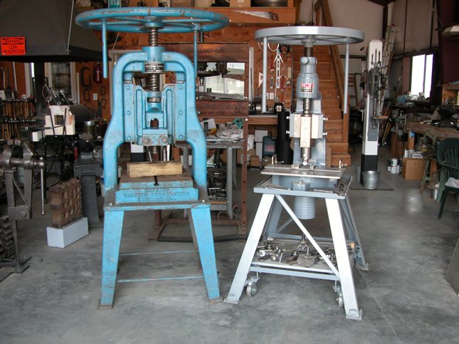
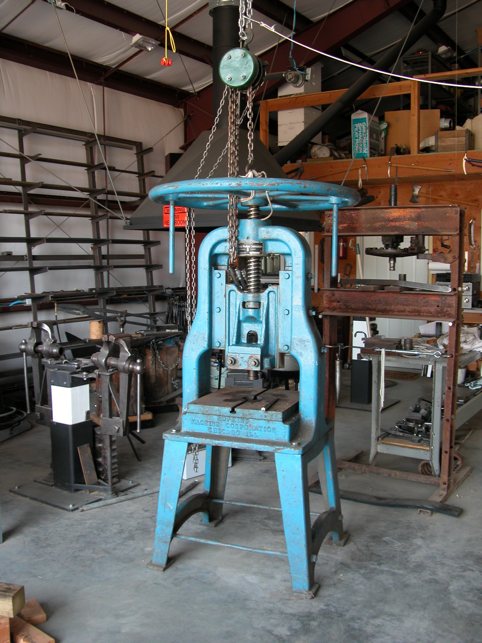
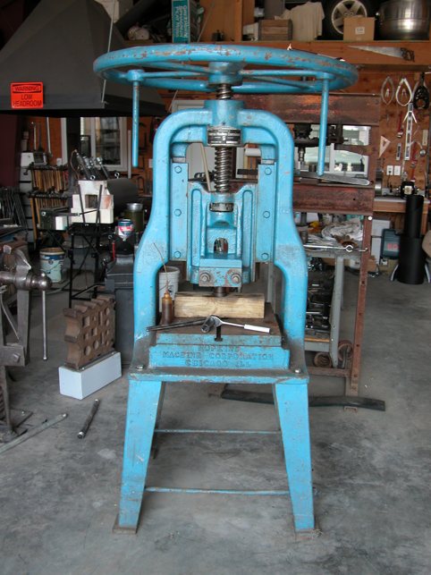
![]() The fly-presses sold
by Dan Morris of "Old World Anvils" are produced by "Karachi
Engineering
& Foundry Works" in Jamnagar, India. I was at first hesitant
about buying
a press made in India or China, but I buried my concern and ordered a
#6.
When it arrived I was extremely pleased with the quality of the
machine.
The only down side was the hardwood crate. It had taken some heavy
abuse
between India and my shop. The flywheel and the press were scuffed in a
few
places, and the paint rubbed off, especially on the flywheel. These
were
strictly cosmetic problems that were easy enough to cure. All unpainted
metal
parts came coated with some kind of rust inhibiting material that I
found
could easily be removed with a rag and WD-40. Soon it was clean and
operating
smoothly, and showed no rust from its long trip half way around the
world.
The fly-presses sold
by Dan Morris of "Old World Anvils" are produced by "Karachi
Engineering
& Foundry Works" in Jamnagar, India. I was at first hesitant
about buying
a press made in India or China, but I buried my concern and ordered a
#6.
When it arrived I was extremely pleased with the quality of the
machine.
The only down side was the hardwood crate. It had taken some heavy
abuse
between India and my shop. The flywheel and the press were scuffed in a
few
places, and the paint rubbed off, especially on the flywheel. These
were
strictly cosmetic problems that were easy enough to cure. All unpainted
metal
parts came coated with some kind of rust inhibiting material that I
found
could easily be removed with a rag and WD-40. Soon it was clean and
operating
smoothly, and showed no rust from its long trip half way around the
world.
![]() I
will add the tooling
to the bottom of this page as I make it, or as people send me
information
and pictures of their fly-press and tooling. If you have a fly-press,
and
have tooling and information that others could use, please share it
with
me so I can add it to this page. I will most certainly credit you with
your
work and images. Contact me if you have any questions, or wish to add
some
of your own fly-press tooling to this page. Thank you.
I
will add the tooling
to the bottom of this page as I make it, or as people send me
information
and pictures of their fly-press and tooling. If you have a fly-press,
and
have tooling and information that others could use, please share it
with
me so I can add it to this page. I will most certainly credit you with
your
work and images. Contact me if you have any questions, or wish to add
some
of your own fly-press tooling to this page. Thank you.
![]()
The Journey Begins
![]() The path to having my
fly-press sitting here in my shop on its mobile drop down caster
mounted
stand has been a long one. I have been aware of fly-presses for many
years, but living in the western US I have not had any opportunities to
actually
see one, let alone see one in action. I occasionally came across some
comment
about, or reference to, a fly-press, and they wet my desire for more
information.
The thing that bothered me most was having to buy used equipment of
this
type, due to there not being any new fly-presses commercially available
in
the US. Dan Morris changed all
that when he started importing fly-presses from India several years
ago.
His company, Old
World Anvils,
came
to my attention through a friend of mine, and I was soon studying the
specs
on the various models of fly-presses that Dan had to offer, the details
of
which are listed on his extensive web site. I understand that Old World
Anvils has now been sold, but when I recently ordered a #P-0 press
from the new owners I got almost instant service. The press arrived in
under a week.
The path to having my
fly-press sitting here in my shop on its mobile drop down caster
mounted
stand has been a long one. I have been aware of fly-presses for many
years, but living in the western US I have not had any opportunities to
actually
see one, let alone see one in action. I occasionally came across some
comment
about, or reference to, a fly-press, and they wet my desire for more
information.
The thing that bothered me most was having to buy used equipment of
this
type, due to there not being any new fly-presses commercially available
in
the US. Dan Morris changed all
that when he started importing fly-presses from India several years
ago.
His company, Old
World Anvils,
came
to my attention through a friend of mine, and I was soon studying the
specs
on the various models of fly-presses that Dan had to offer, the details
of
which are listed on his extensive web site. I understand that Old World
Anvils has now been sold, but when I recently ordered a #P-0 press
from the new owners I got almost instant service. The press arrived in
under a week.
![]() One thing that immediately
impressed me when I was communicating with Dan, was how
quickly his
presses sold out. He receives periodic shipments from India, and almost
all
of them are sold before the ship arrives in port. I was fortunate and
was
able to lock in the purchase of his last #6 press. I
also wanted
to buy a #P-0 fly-press, for use in my Repousse' work, but I was too
late. However, I recently was able to obtain one.
One thing that immediately
impressed me when I was communicating with Dan, was how
quickly his
presses sold out. He receives periodic shipments from India, and almost
all
of them are sold before the ship arrives in port. I was fortunate and
was
able to lock in the purchase of his last #6 press. I
also wanted
to buy a #P-0 fly-press, for use in my Repousse' work, but I was too
late. However, I recently was able to obtain one.
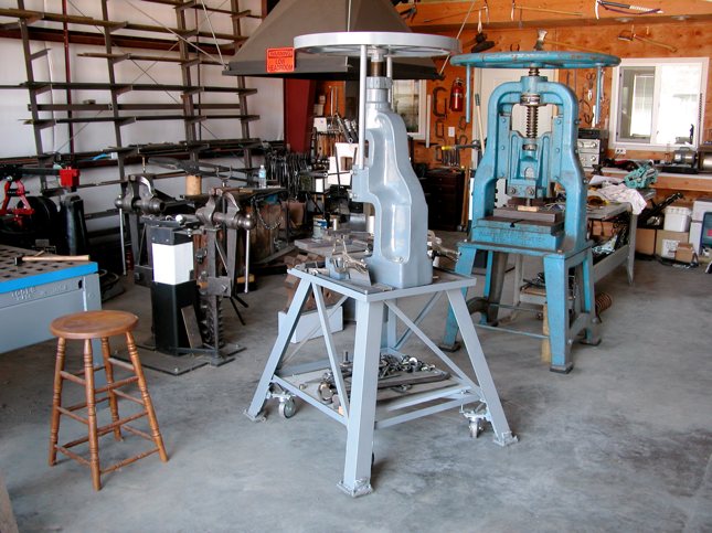
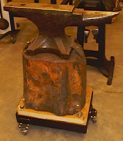
![]() The single most difficult
part of the whole adventure was the construction of my mobile press
stand.
Due to the inertia that the fly-press' flywheel creates, the stand has
to
be well grounded on the shop floor, so it can't be on casters when in
use
or the whole stand will rotate each time the press ram contacts the
work.
That means having to design a way to lower the casters, or raise the
stand.
That is a tall order when the stand and press together weigh roughly a
thousand
pounds. No light gage hardware store hinges will work for that kind of
application,
so I would have to come up with a design that would be really skookum
(hell
for stout), and be easily engaged when I needed to move the press out
of
the way for other work. I went through many different designs, but
finally
settled on a hinged design that allows me to easily drop the stand down
on
to its high friction foot pads. When the stand is on its casters I can
easily
move it with only the force of two fingers, but changing its direction
takes
a little more force. The posted images are shown with the stand on its
casters.
It may not look like it, but that is because the casters only raise the
stand's
foot pads 1/2" above the floor for safety in case a caster, or a caster
bracket, should fail. I didn't want there to be any possibility the
stand
and fly-press could be overturned accidentally.
The single most difficult
part of the whole adventure was the construction of my mobile press
stand.
Due to the inertia that the fly-press' flywheel creates, the stand has
to
be well grounded on the shop floor, so it can't be on casters when in
use
or the whole stand will rotate each time the press ram contacts the
work.
That means having to design a way to lower the casters, or raise the
stand.
That is a tall order when the stand and press together weigh roughly a
thousand
pounds. No light gage hardware store hinges will work for that kind of
application,
so I would have to come up with a design that would be really skookum
(hell
for stout), and be easily engaged when I needed to move the press out
of
the way for other work. I went through many different designs, but
finally
settled on a hinged design that allows me to easily drop the stand down
on
to its high friction foot pads. When the stand is on its casters I can
easily
move it with only the force of two fingers, but changing its direction
takes
a little more force. The posted images are shown with the stand on its
casters.
It may not look like it, but that is because the casters only raise the
stand's
foot pads 1/2" above the floor for safety in case a caster, or a caster
bracket, should fail. I didn't want there to be any possibility the
stand
and fly-press could be overturned accidentally.
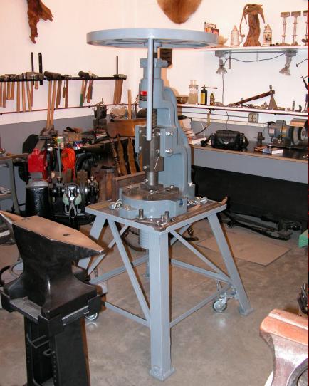
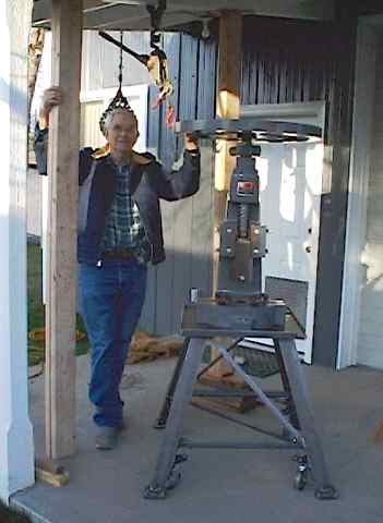
![]() The next big problem
to solve was how to lift the 700 pound press up on to its stand once
the
stand was completed. I thought through many different methods, but it
soon
all came together. I was able to very easily lift the press into place
on
the stand, without spending an additional penny on any rental
equipment,
other than on three 1/2" bolts to bolt my forged suspension hook
bracket
to my shop's patio roof carrier beam. I had a 3000 pound "come-along"
in
my shed, and it easily lifted the press high enough for me to roll the
stand
under the press and then lower it right on to its mounting bolt holes.
It
all went so smoothly that is was totally anti-climactic.
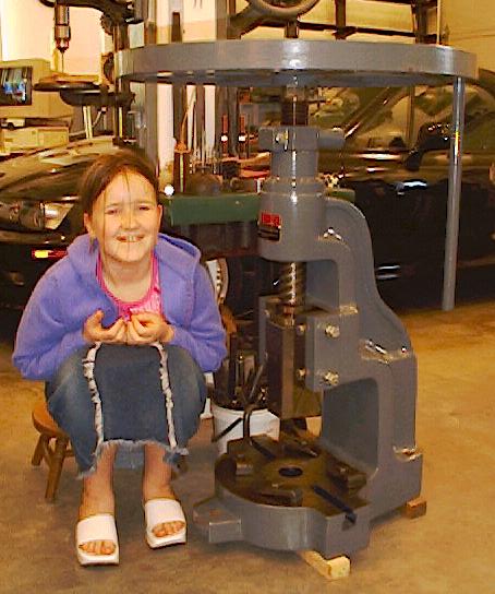
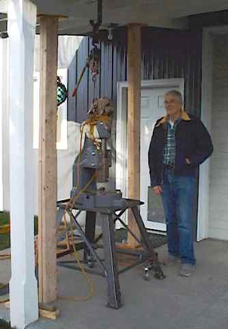
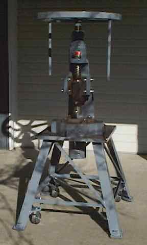
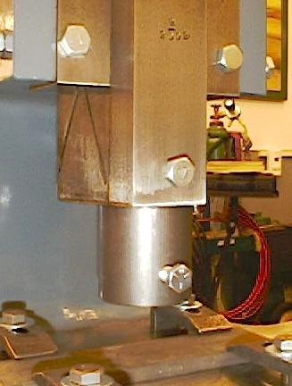
This image was
taken about 3 minutes after
the press was seated on the stand. You can see the forged suspension
hook
bracket bolted to the carrier beam, the doubled 2x6 "stiff-backs" under
the
beam, and my come-along still hanging above the press. I also have the
press
wrapped in rags to prevent my retired climbing rope from marking its
smoothly
finished surface. The gentleman with the press is a dear
friend, Zeph,
who always generously offers his help when I most need it. In this
image the press and its
stand are now free, and
easily moved by a very gentle pressure from a finger or two. Time for a
beer.
The next big problem
to solve was how to lift the 700 pound press up on to its stand once
the
stand was completed. I thought through many different methods, but it
soon
all came together. I was able to very easily lift the press into place
on
the stand, without spending an additional penny on any rental
equipment,
other than on three 1/2" bolts to bolt my forged suspension hook
bracket
to my shop's patio roof carrier beam. I had a 3000 pound "come-along"
in
my shed, and it easily lifted the press high enough for me to roll the
stand
under the press and then lower it right on to its mounting bolt holes.
It
all went so smoothly that is was totally anti-climactic.
This image was
taken about 3 minutes after
the press was seated on the stand. You can see the forged suspension
hook
bracket bolted to the carrier beam, the doubled 2x6 "stiff-backs" under
the
beam, and my come-along still hanging above the press. I also have the
press
wrapped in rags to prevent my retired climbing rope from marking its
smoothly
finished surface. The gentleman with the press is a dear
friend, Zeph,
who always generously offers his help when I most need it. In this
image the press and its
stand are now free, and
easily moved by a very gentle pressure from a finger or two. Time for a
beer.
![]()
The Mobile Fly-press Stand
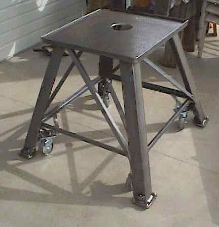
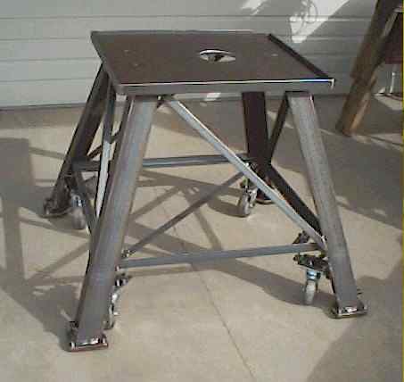
![]() The biggest consideration
when I designed and built the mobile stand was strength. Not only does
it
have to support the 700 pounds of the press, but it has to stand up to
the
very significant torque that is transferred to the stand each time the
flywheel
comes to an abrupt stop as the tool encounters the work. I elected to
counter
the torque by using diagonal braces
of 1" by 3/16"
equal leg angle iron in the diagonal direction of tension
in each
of the four bays. I also welded in a diagonal brace across the
horizontal
span between two of the legs.
The biggest consideration
when I designed and built the mobile stand was strength. Not only does
it
have to support the 700 pounds of the press, but it has to stand up to
the
very significant torque that is transferred to the stand each time the
flywheel
comes to an abrupt stop as the tool encounters the work. I elected to
counter
the torque by using diagonal braces
of 1" by 3/16"
equal leg angle iron in the diagonal direction of tension
in each
of the four bays. I also welded in a diagonal brace across the
horizontal
span between two of the legs.
![]() The legs are fabricated
from 1/4" x 3" equal leg angle iron, the foot pads from 1/4" plate, the
table
top from 1/2" plate, and the rail around the table top from 1-1/2" x
3/16"
equal leg angle iron. All weld connections were beveled on both sides,
and
welded front and back with 70 ksi welding rod (7014). The foot pads
have
elastomeric high friction conveyor belting cut to fit, and bolted into
place
with 1/4" carriage bolts, heads down. The bolt heads pull up into the
belt
material deeply enough so they will not come in contact with the floor.
This
was left-over belting that I used under my power hammer.
The legs are fabricated
from 1/4" x 3" equal leg angle iron, the foot pads from 1/4" plate, the
table
top from 1/2" plate, and the rail around the table top from 1-1/2" x
3/16"
equal leg angle iron. All weld connections were beveled on both sides,
and
welded front and back with 70 ksi welding rod (7014). The foot pads
have
elastomeric high friction conveyor belting cut to fit, and bolted into
place
with 1/4" carriage bolts, heads down. The bolt heads pull up into the
belt
material deeply enough so they will not come in contact with the floor.
This
was left-over belting that I used under my power hammer.
![]() I elected to splay the
legs out diagonally. I wanted to spread the footprint of the stand to
increase
its stability once the heavy press was bolted in place. Having
so many
angles complicates the fabrication, but it is not overly difficult to
work
with. The only really difficult moment came when welding the legs to
the
1/2" steel plate. Holding them in position for the welding was greatly
simplified
by having my apprentice, Kevin, wear my spare welding helmet while
holding
the legs carefully in exact alignment as I tacked them in place for
further
welding. After tack welding them I checked the diagonal measurements,
pulled
two string lines across the diagonals of all four legs at the same time
to
insure all four feet would be on the same plane, and just in general
checked
everything for trueness. Then I completed the welding of both sides of
the
angle iron legs. Once the legs were attached, the rest was just a
matter
of filling in the gaps, and was easily accomplished with screw clamps
to
hold the diagonal members in position for welding. Not being an expert
welder,
I like to do as much welding as possible in the flat position, so I had
to
constantly reposition the stand as I progressed. That became quite a
chore
when the weight increased to around 200 pounds. Nevertheless it was
within
my limits, and it got done in a timely fashion. The welds came out
smooth
and clean.
I elected to splay the
legs out diagonally. I wanted to spread the footprint of the stand to
increase
its stability once the heavy press was bolted in place. Having
so many
angles complicates the fabrication, but it is not overly difficult to
work
with. The only really difficult moment came when welding the legs to
the
1/2" steel plate. Holding them in position for the welding was greatly
simplified
by having my apprentice, Kevin, wear my spare welding helmet while
holding
the legs carefully in exact alignment as I tacked them in place for
further
welding. After tack welding them I checked the diagonal measurements,
pulled
two string lines across the diagonals of all four legs at the same time
to
insure all four feet would be on the same plane, and just in general
checked
everything for trueness. Then I completed the welding of both sides of
the
angle iron legs. Once the legs were attached, the rest was just a
matter
of filling in the gaps, and was easily accomplished with screw clamps
to
hold the diagonal members in position for welding. Not being an expert
welder,
I like to do as much welding as possible in the flat position, so I had
to
constantly reposition the stand as I progressed. That became quite a
chore
when the weight increased to around 200 pounds. Nevertheless it was
within
my limits, and it got done in a timely fashion. The welds came out
smooth
and clean.
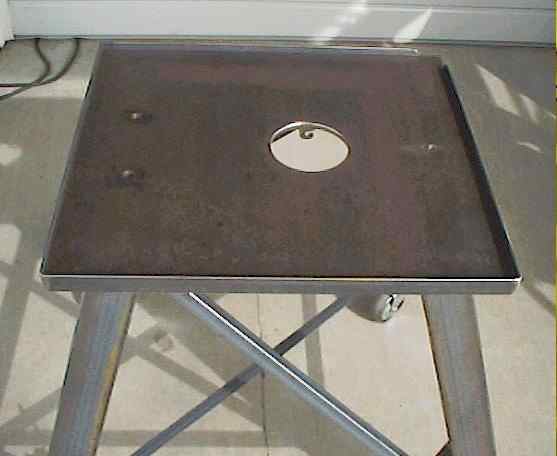
![]() Part way through the
construction, Dan mentioned in an e-mail that a hole
in the table top under the press would be a good
idea to allow the
scale, and any punchings, to drop through into a bucket under the table
surface.
That seemed like a really good idea, so I torched out a 5" diameter
hole
in the correct location, and ground it smooth and true. I also welded
two
hooks I made from 1" equal leg angle iron on either side of the hole to
hang
a bucket on directly under the hole. One of the hooks is
visible through
the hole on the far side in the above linked image. I had
predrilled
the 1/2" press mounting holes in the plate prior to doing any welding.
In
the image you can see that a small section of the table rail
has been
removed in the far right corner. I cut away the rail to the level of
the
table top in order to have a small gap to sweep scale and other debris
off
the table easily. Otherwise the enclosed surface would be constantly
full
of debris that would be difficult to remove. That corner is the front
right
corner when the press is in position on the stand. Also, the rail
around
the table was welded together into a frame prior to placing the plate
inside
for welding. I ground the lower edge of the plate to match the radius
in
the interior corner of the angle iron so that the contact would be
tight
between the plate edge and the angle iron railing. In
fact the
frame was so tight that I had to drive it into place with a 4 pound
hammer,
using a 2x4 for a pad. The contact between the two is extremely tight,
leaving
no room for debris to collect.
Part way through the
construction, Dan mentioned in an e-mail that a hole
in the table top under the press would be a good
idea to allow the
scale, and any punchings, to drop through into a bucket under the table
surface.
That seemed like a really good idea, so I torched out a 5" diameter
hole
in the correct location, and ground it smooth and true. I also welded
two
hooks I made from 1" equal leg angle iron on either side of the hole to
hang
a bucket on directly under the hole. One of the hooks is
visible through
the hole on the far side in the above linked image. I had
predrilled
the 1/2" press mounting holes in the plate prior to doing any welding.
In
the image you can see that a small section of the table rail
has been
removed in the far right corner. I cut away the rail to the level of
the
table top in order to have a small gap to sweep scale and other debris
off
the table easily. Otherwise the enclosed surface would be constantly
full
of debris that would be difficult to remove. That corner is the front
right
corner when the press is in position on the stand. Also, the rail
around
the table was welded together into a frame prior to placing the plate
inside
for welding. I ground the lower edge of the plate to match the radius
in
the interior corner of the angle iron so that the contact would be
tight
between the plate edge and the angle iron railing. In
fact the
frame was so tight that I had to drive it into place with a 4 pound
hammer,
using a 2x4 for a pad. The contact between the two is extremely tight,
leaving
no room for debris to collect.
![]() I finally got a long
enough break in the weather to get the stand painted. Here is an
image showing the stand on
the patio after the
painting was complete. It is back up on its casters in the
image. It
was quite a job, because I had to roll it out on to a sheet of plastic,
lower
it on to its foot-pads, then remove the casters. I could then get the
caster
brackets painted underneath and on top, as well as all the other
surfaces
on the stand, both exposed and hidden. This image also shows the can
that
is suspended by the two hooks under the hole. It received a coat of
paint
also. I also repainted the flywheel and the two down-handles, as the
paint
on them had been scraped pretty badly during shipment. The press is now
safely
back in the shop, and is finally 100% ready for service. :-)
I finally got a long
enough break in the weather to get the stand painted. Here is an
image showing the stand on
the patio after the
painting was complete. It is back up on its casters in the
image. It
was quite a job, because I had to roll it out on to a sheet of plastic,
lower
it on to its foot-pads, then remove the casters. I could then get the
caster
brackets painted underneath and on top, as well as all the other
surfaces
on the stand, both exposed and hidden. This image also shows the can
that
is suspended by the two hooks under the hole. It received a coat of
paint
also. I also repainted the flywheel and the two down-handles, as the
paint
on them had been scraped pretty badly during shipment. The press is now
safely
back in the shop, and is finally 100% ready for service. :-)
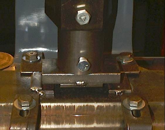
The Retractable Caster Mounting
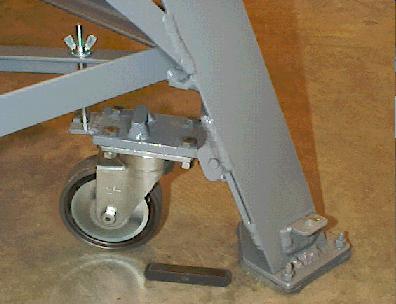
![]() The retractable caster
mounting is clearly, but not completely, shown in the
image I have provided. It
is shown in the "relaxed,"
or up position, with the foot pad on the floor. What is missing is the
short
diagonal brace, laying on the floor, that is inserted between the short
block
of 1/2" square stock, which is visible welded on the top of the hinge
plate,
and a similar block above it that is welded on the bottom of the
support
plate that the braces between the legs are anchored to. The short
diagonal
brace is made from 1/2" square stock, and is about 3-1/2" long. It is
ground
on each end to have a 90 degree chisel end to match the slot it braces
into.
The retractable caster
mounting is clearly, but not completely, shown in the
image I have provided. It
is shown in the "relaxed,"
or up position, with the foot pad on the floor. What is missing is the
short
diagonal brace, laying on the floor, that is inserted between the short
block
of 1/2" square stock, which is visible welded on the top of the hinge
plate,
and a similar block above it that is welded on the bottom of the
support
plate that the braces between the legs are anchored to. The short
diagonal
brace is made from 1/2" square stock, and is about 3-1/2" long. It is
ground
on each end to have a 90 degree chisel end to match the slot it braces
into.
![]() The picture shows the
caster bracket in the "up" position, with the foot pad solidly on the
floor.
When the leg is lifted, by using a lifting tool that sockets into the
little
forged angle tab that is welded on the lower leg, the 1/2" diagonal
brace
can very easily be inserted, and then the stand is lowered down to rest
with
the foot pad 1/2" above the floor. The bolt
with the wing nut
is used to keep the hinged bracket solidly up against its diagonal
brace
when the stand is rolling across my somewhat uneven floor which lifts
it
off the floor periodically.
The picture shows the
caster bracket in the "up" position, with the foot pad solidly on the
floor.
When the leg is lifted, by using a lifting tool that sockets into the
little
forged angle tab that is welded on the lower leg, the 1/2" diagonal
brace
can very easily be inserted, and then the stand is lowered down to rest
with
the foot pad 1/2" above the floor. The bolt
with the wing nut
is used to keep the hinged bracket solidly up against its diagonal
brace
when the stand is rolling across my somewhat uneven floor which lifts
it
off the floor periodically.
![]() The hinge pin is 3/8"
cold rolled that was welded full width across its contact with the 3/8"
thick
hinge plate. I beveled the plate on both sides so that I obtained full
penetration in the weld, then ground the weld smooth and flush with the
plate.
I used 7014 rod. The female part of the hinge is welded into place
flush
against the side of the hinge plate to eliminate any bending moment in
the
3/8" rod. I tested the assembly in its worst
case position, when
the caster is rotated 90 degrees to the side, by loading the corner of
the
press stand with over a thousand pounds of weight. The
caster
bracket was rock solid. Since the worst case load when in use is only
about
500 pounds, I feel it is totally safe. Also, the 1/2" height that the
foot
pad is above the floor when being moved provides additional security
should
the bracket or caster ever fail.
The hinge pin is 3/8"
cold rolled that was welded full width across its contact with the 3/8"
thick
hinge plate. I beveled the plate on both sides so that I obtained full
penetration in the weld, then ground the weld smooth and flush with the
plate.
I used 7014 rod. The female part of the hinge is welded into place
flush
against the side of the hinge plate to eliminate any bending moment in
the
3/8" rod. I tested the assembly in its worst
case position, when
the caster is rotated 90 degrees to the side, by loading the corner of
the
press stand with over a thousand pounds of weight. The
caster
bracket was rock solid. Since the worst case load when in use is only
about
500 pounds, I feel it is totally safe. Also, the 1/2" height that the
foot
pad is above the floor when being moved provides additional security
should
the bracket or caster ever fail.
![]() When I was grinding
the braces to hold the hinge in its locked down position I had the
stand
upside down and ground them so that the surfaces of the caster wheels
were
all on the same plane. That caused each diagonal brace to be slightly
different
in length from the others. To prevent mixing them up, I stamped a
number
into each one, and a corresponding number into each leg. They lay on
the
back of the stand table, behind the press, when not in use.
When I was grinding
the braces to hold the hinge in its locked down position I had the
stand
upside down and ground them so that the surfaces of the caster wheels
were
all on the same plane. That caused each diagonal brace to be slightly
different
in length from the others. To prevent mixing them up, I stamped a
number
into each one, and a corresponding number into each leg. They lay on
the
back of the stand table, behind the press, when not in use.
![]() Although this system
took a lot of time and care to fabricate, using it is a piece of cake.
It
is very easy for me to use the forged lifting tool with my left hand,
which
sockets into the forged angle-iron fitting welded to the leg, visible
just
above the foot pad, to raise each leg while I insert the diagonal brace
into
place with my right hand. It is much harder to describe than to do. I
then
tighten up the wing nut on the locking bolt, and after doing all four,
the
stand is ready to be rolled to wherever it needs to go. Lowering it
back
down to the floor is even easier.
Although this system
took a lot of time and care to fabricate, using it is a piece of cake.
It
is very easy for me to use the forged lifting tool with my left hand,
which
sockets into the forged angle-iron fitting welded to the leg, visible
just
above the foot pad, to raise each leg while I insert the diagonal brace
into
place with my right hand. It is much harder to describe than to do. I
then
tighten up the wing nut on the locking bolt, and after doing all four,
the
stand is ready to be rolled to wherever it needs to go. Lowering it
back
down to the floor is even easier.
Tools and Tooling
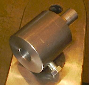
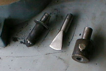
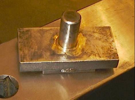
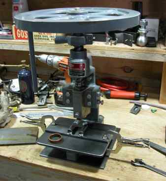
![]() The first tool that
should be made is an "integral
tool-holder"
for the ram face. This tool is a "false" tool holding socket that
fits into the socket in the ram face.
It prevents
wear or damage to the ram face, or the tool holding bolt and socket,
during
use of the fly-press. The integral tool-holder in the image is 3"
along the side of the body, 3" in diameter, has a 1" by 2"
hole for
the tool shanks to socket into, and a 1" x 2" shank
(male part)
to fit the hole in the ram face. The locking bolt is a 1/2" bolt. I
also
filed a small curved groove into the shank slightly above the point
where
the tool locking bolt on the ram strikes it. This causes the
shank to
be pulled tightly up into the hole in the ram face so that it can't be
pulled
out if a tool sticks in hot iron. I have to thank
Rex Price
of
Hybridburners.com
for machining
this fine tool for me.
The first tool that
should be made is an "integral
tool-holder"
for the ram face. This tool is a "false" tool holding socket that
fits into the socket in the ram face.
It prevents
wear or damage to the ram face, or the tool holding bolt and socket,
during
use of the fly-press. The integral tool-holder in the image is 3"
along the side of the body, 3" in diameter, has a 1" by 2"
hole for
the tool shanks to socket into, and a 1" x 2" shank
(male part)
to fit the hole in the ram face. The locking bolt is a 1/2" bolt. I
also
filed a small curved groove into the shank slightly above the point
where
the tool locking bolt on the ram strikes it. This causes the
shank to
be pulled tightly up into the hole in the ram face so that it can't be
pulled
out if a tool sticks in hot iron. I have to thank
Rex Price
of
Hybridburners.com
for machining
this fine tool for me.
![]() Here are some more tools
for a #4 fly-press, and a pressed candle holder socket, courtesy of
Larry Zoeller.
Larry's
press is smaller than my #6, but the tooling design will be identical,
just
a little smaller. Thanks for sharing these images with us Larry.
Here are some more tools
for a #4 fly-press, and a pressed candle holder socket, courtesy of
Larry Zoeller.
Larry's
press is smaller than my #6, but the tooling design will be identical,
just
a little smaller. Thanks for sharing these images with us Larry.
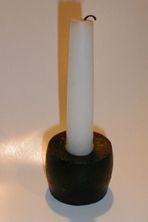
Integral Tool-holder and a Hot Cut made for Larry's #4 Press
Adjustable Work Support Platform
Candle Socket Pressed Out of a Section of Round Bar Stock
Removable Caster Brackets
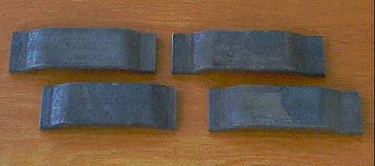
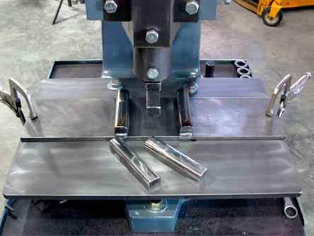
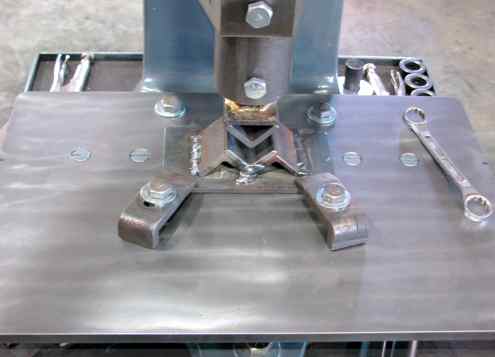
![]() I needed to make some
removable caster brackets for the frame that will hold my work-station
anvil.
The frame will have three removable casters to allow me to move the
work-station
into a corner when not needed. When I made the brackets
for the Kohlswa anvil, they took a lot of
hammering, and many
heats, to get the 1-1/2" x 1/4" stock formed into the needed shape. The
brackets
were anything but perfect, but did the job. I decided to try using the
new
fly-press to make this next set. I used scrap iron to make the
dies. The top die was made
by mounting a section of 1" round stock in the fly press tool holder
and
ramming it 3/8" into the 3/4" thick top die plate when it was at a
yellow
heat. I had ground an index bevel on one side of the edge of the round
bar
so that I would be able to reposition it back into the hole exactly for
sweat
brazing it together later.
I needed to make some
removable caster brackets for the frame that will hold my work-station
anvil.
The frame will have three removable casters to allow me to move the
work-station
into a corner when not needed. When I made the brackets
for the Kohlswa anvil, they took a lot of
hammering, and many
heats, to get the 1-1/2" x 1/4" stock formed into the needed shape. The
brackets
were anything but perfect, but did the job. I decided to try using the
new
fly-press to make this next set. I used scrap iron to make the
dies. The top die was made
by mounting a section of 1" round stock in the fly press tool holder
and
ramming it 3/8" into the 3/4" thick top die plate when it was at a
yellow
heat. I had ground an index bevel on one side of the edge of the round
bar
so that I would be able to reposition it back into the hole exactly for
sweat
brazing it together later.
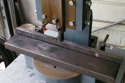
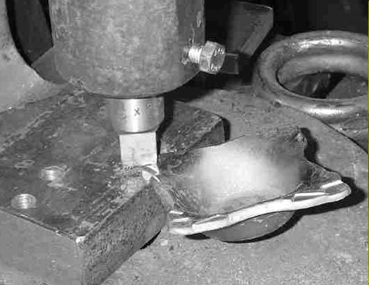
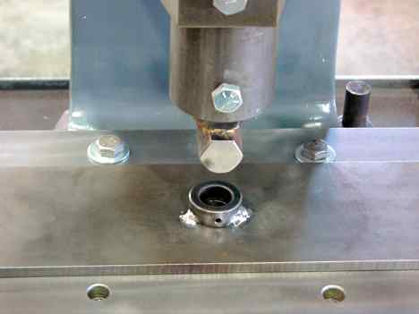
![]() The whole process went
amazingly well. Once the dies were completed, I cut 10" of 1-1/2" x
1/4"
stock, took a heat on one half of it, and placed it into the press. It
took
only two relatively gentle "bumps" with the press to bottom the die and
create
a perfect bracket..all in 10 seconds or less. I "bumped" it a couple
times
more to be certain the bends were complete, and then took a second heat
to
do the other end. Ten minutes later I had
four perfect brackets
that had no twist, bend,
or warp, as indicated when I placed the 10" long bar, with the two
bracket
shapes pressed into it, on the anvil. It was absolutely true, and had
no
wobble or twist. What would have taken me several hours to hammer out
manually,
and quite a number of heats, was done in ten minutes, and in four
heats,
and the result many times better in quality.
The whole process went
amazingly well. Once the dies were completed, I cut 10" of 1-1/2" x
1/4"
stock, took a heat on one half of it, and placed it into the press. It
took
only two relatively gentle "bumps" with the press to bottom the die and
create
a perfect bracket..all in 10 seconds or less. I "bumped" it a couple
times
more to be certain the bends were complete, and then took a second heat
to
do the other end. Ten minutes later I had
four perfect brackets
that had no twist, bend,
or warp, as indicated when I placed the 10" long bar, with the two
bracket
shapes pressed into it, on the anvil. It was absolutely true, and had
no
wobble or twist. What would have taken me several hours to hammer out
manually,
and quite a number of heats, was done in ten minutes, and in four
heats,
and the result many times better in quality.
![]() This was my first time
actually making something with the press. It was quite an eye opener. I
was
amazed at how easily the press could form the four
bends in the 1/4"
stock all at the same time so easily. The force that the press
generates
is amazing. The almost total lack of effort on my part to operate the
press
was also amazing to me. I wish this tool had come into my life many
years
ago. Frankly, for my shop and many others too this is a superior
alternative
to a hydraulic press.
This was my first time
actually making something with the press. It was quite an eye opener. I
was
amazed at how easily the press could form the four
bends in the 1/4"
stock all at the same time so easily. The force that the press
generates
is amazing. The almost total lack of effort on my part to operate the
press
was also amazing to me. I wish this tool had come into my life many
years
ago. Frankly, for my shop and many others too this is a superior
alternative
to a hydraulic press.
Gene Chapman
![]() The following series
of images shows and describes some of Gene Chapman's tooling and work
which
he has done using a tow ball for his ram tool. This may provide some
good
ideas for other projects where similar forming may be needed. Tow balls
are
easy to obtain and come in a variety of sizes, as well as various shaft
diameters, so there are a lot of possibilities available to the
fly-press
operator using these simple tools. Gene has been doing a lot of work
with
his press, and may be well worth your time to contact if you are
tooling
up your own fly-press. Please visit his web page at
www.oakandiron.com.
I will quote Gene's own words to describe these images.
The following series
of images shows and describes some of Gene Chapman's tooling and work
which
he has done using a tow ball for his ram tool. This may provide some
good
ideas for other projects where similar forming may be needed. Tow balls
are
easy to obtain and come in a variety of sizes, as well as various shaft
diameters, so there are a lot of possibilities available to the
fly-press
operator using these simple tools. Gene has been doing a lot of work
with
his press, and may be well worth your time to contact if you are
tooling
up your own fly-press. Please visit his web page at
www.oakandiron.com.
I will quote Gene's own words to describe these images.
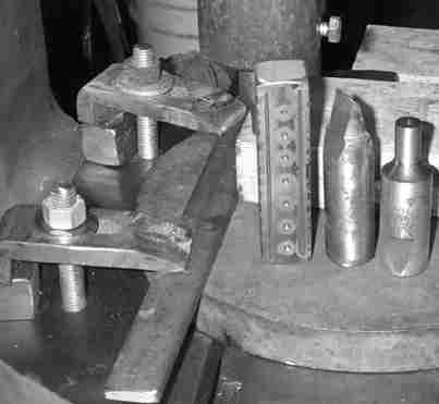
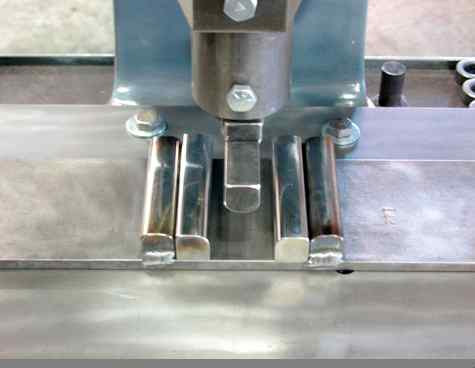
"I ground a grooving tool out of one of the 1" Whitney type punches this morning. A simple 1/4 X 1" fence was bolted down on the press table. Parallel grooves were bumped into a cold piece of mild steel. Small punch marks were centered in the steel on 1/2" intervals, nothing spectacular but I'm learning. The fence was marked with a aluminum pencil in 1/2" increments. Hmmm, a magnetic ruler that could be stuck to the fence would be nice."
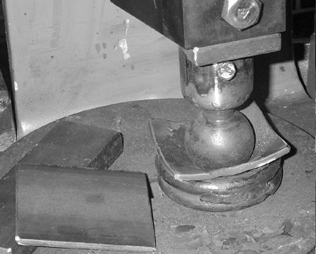
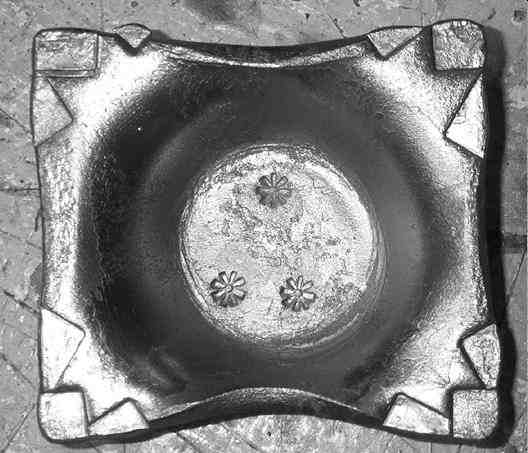
"I'm making half a dozen small dished out holders. Material is 3/16" X 3 X 3 1/2 mild steel flat bar. All these steps are done hot. Dishing bottom with trailer hitch ball."
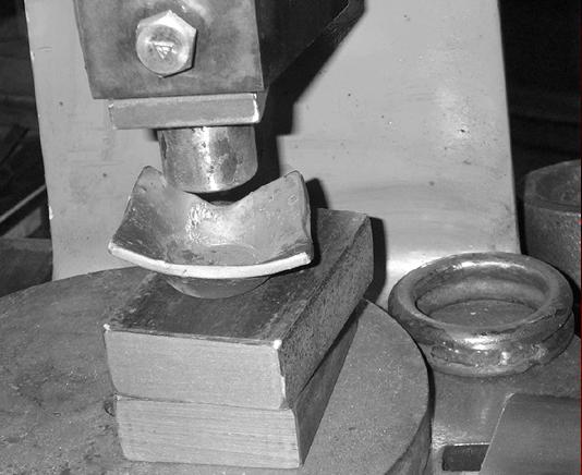
"Next the rounded bottom is flattened with the tool holder, it's 1 1/2" in diameter. In the right background are two 1/2" rings welded together, these were used for dishing out."
"The sides were flattened with a tool made from two pieces of three inch angle iron, and some scrap. It works fairly well with the press."
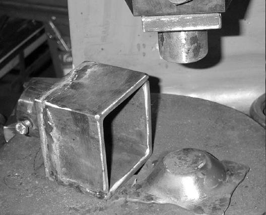
"The corners are squished with a commercial punch. This is done on the diamond. Each corner comes out a bit different, I'll just call it "ART."
"I decorated the bottom of the dish three times with my touch-mark then hot wire brushed the piece."
"Close up of the top of the dish. All the high heats left a slightly rough texture on the steel. This was a fun project, got to play and make some goodies."
![]() Here is an additional
post that Gene made on the forum where he quotes Joe Walters, that has
some
very good information, and is quoted exactly as posted, except that I
have
removed spaces between some sentences.
Here is an additional
post that Gene made on the forum where he quotes Joe Walters, that has
some
very good information, and is quoted exactly as posted, except that I
have
removed spaces between some sentences.
Ray, this is a reprint of Joe Walters post on fly presses from the first Fly Press thread.
"I've got an old Adam's 3A fly-press, the press weighs in around 300 lbs. I use it ALL the time, mainly for texturing, straightening, flatting, and squishing welds closed. Also for bumping shoulders into blades. A hot cutter is a joy, very precise cuts. I also have 1inch square dies which are beveled and rounded to squish in flats for late night forging. It works very well and is very precise (just think of 1" skewed hammer heads with rounded edges). What I've learned is that you have to use the smallest tooling possible for forging, i.e., a 1" hammer head maximum on my press, yours looks a little more robust. And the steel has to be worked HOT. Like near welding heat on simple steels. Large bends or arcs as well as cutting can be done at a much lower heat, or cold.
I use squaring dies to take 1" bites into canned Damascus and it welds things up solid with one pass. I can usually get about 5 inches welded in one heat. I read on a website a suggestion to slow down and not wail away on the tool. Well, I go fast and wail like hell when drawing (after I developed the feel for it, anyways), and I get a lot more done in one heat, but maybe "fast" and "wail" are relative terms?
I break down round stock too, again, very hot steel, one inch bites. 1.25" W-1 breaks down like clay, but It's not a "gentle bump" or "squeeze," It's a windup and a big fast push. By the time the handle winds down the the stop collar, the speed has slowed down enough to not cause any damage or abnormal wear.
There are a lot of uses for them in knife work, besides
setting pins, so
don't give up! Just remember, Hot steel + small tool = easily squished
metal."
![]() I have
not had time to do much work on this web site
for quite some time because of having retired, and moving to small
horse
ranch in the mountains of central Idaho. Also, I have developed some
medical issues that have set me back significantly, but that is another
story. Between plowing snow,
snow, and more snow, and caring for our
three horses and one miniature donkey, I have been
working on my fly-press tooling. I bought a new press, a tiny "P-0"
to go with the big P-6, and have been making matching tooling for both.
The P-0 is shown with off-set bending tooling in the
image, and the perfectly round copper ring was a test piece produced
with that
tooling. I obtained the P-0 primarily for veining leaves for my
Repousse' work, and as a veiner it functions extremely well, providing
much greater
control and smoother veining lines than can easily be done by
hammering.
I have
not had time to do much work on this web site
for quite some time because of having retired, and moving to small
horse
ranch in the mountains of central Idaho. Also, I have developed some
medical issues that have set me back significantly, but that is another
story. Between plowing snow,
snow, and more snow, and caring for our
three horses and one miniature donkey, I have been
working on my fly-press tooling. I bought a new press, a tiny "P-0"
to go with the big P-6, and have been making matching tooling for both.
The P-0 is shown with off-set bending tooling in the
image, and the perfectly round copper ring was a test piece produced
with that
tooling. I obtained the P-0 primarily for veining leaves for my
Repousse' work, and as a veiner it functions extremely well, providing
much greater
control and smoother veining lines than can easily be done by
hammering.
![]() I want
to recommend you consider obtaining a copy of the DVD video "The Fly
Press" from Teaching
Tapes.net.
This excellent video has information in it that will be very useful to
the beginner as well as the advanced smith using a fly-press. I have
made some modifications in the way John Crouchet, in the video, has his
press tooling set up, but that is to be expected. I am going to provide
information and images here about some of my new tooling, and why I
consider my way of making them to be at least as good as John's, and
perhaps for me, and possibly you, even better and easier.
I want
to recommend you consider obtaining a copy of the DVD video "The Fly
Press" from Teaching
Tapes.net.
This excellent video has information in it that will be very useful to
the beginner as well as the advanced smith using a fly-press. I have
made some modifications in the way John Crouchet, in the video, has his
press tooling set up, but that is to be expected. I am going to provide
information and images here about some of my new tooling, and why I
consider my way of making them to be at least as good as John's, and
perhaps for me, and possibly you, even better and easier.
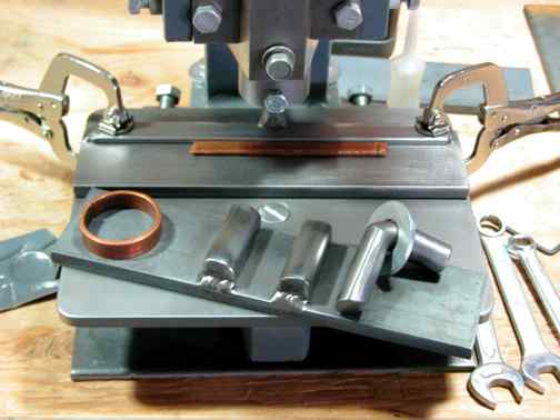
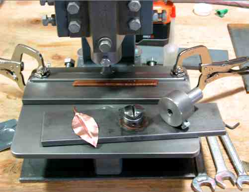
![]() One of
the most useful concepts that John shows you
in his video is the "clamp table" modification to a fly-press. After
some thinking about how best to go about it, I made clamp plates for
both of my presses. The P-6 has a 1/2"
thick plate, shown here with offset bending tooling in place,
and the P-0 uses a 3/8"plate.
The P-0 has my version of a tool holder
bolster plate clamped in place on the clamp plate. Notice the
copper ring on the offset tooling plate in this close-up image of the P-0.
The off-set tooling
allows perfect steel, or non ferrous, rings or bends to be easily
fabricated in
almost any diameter or radius you need. The image of the P-6
with the offset
bending tooling also has two additional unmounted "bending loaves"
shown. The two free bending
loaves fit
between the two loaves
that are shown welded on the bolster plate. I
can simply place one, or both, of the spare loaves between the attached
loaves to reduce the radius, and allow bending of much smaller diameter
circles. This eliminates the need for making several separate bolster
plates. I used 1085 steel for the bending loaves. They were forged
first to reduce the amount of grinding,
then ground to final shape.
One of
the most useful concepts that John shows you
in his video is the "clamp table" modification to a fly-press. After
some thinking about how best to go about it, I made clamp plates for
both of my presses. The P-6 has a 1/2"
thick plate, shown here with offset bending tooling in place,
and the P-0 uses a 3/8"plate.
The P-0 has my version of a tool holder
bolster plate clamped in place on the clamp plate. Notice the
copper ring on the offset tooling plate in this close-up image of the P-0.
The off-set tooling
allows perfect steel, or non ferrous, rings or bends to be easily
fabricated in
almost any diameter or radius you need. The image of the P-6
with the offset
bending tooling also has two additional unmounted "bending loaves"
shown. The two free bending
loaves fit
between the two loaves
that are shown welded on the bolster plate. I
can simply place one, or both, of the spare loaves between the attached
loaves to reduce the radius, and allow bending of much smaller diameter
circles. This eliminates the need for making several separate bolster
plates. I used 1085 steel for the bending loaves. They were forged
first to reduce the amount of grinding,
then ground to final shape.
![]() I have
owned my P-6 for a number of years, but until
I made the clamp plate for it, I have to say that I was operating in a
very inefficient manor. The clamp plate greatly speeds up the changing
of tooling, and provides a far superior surface on which to work. John
uses his hold-down dog bolt holes to mount his clamp plate with, but I
modified his design so that I could still
make use of my previous
tooling
which needs the dogs, without having to modify it for clamp
plate mounting. The two bolt heads visible under the throat of the
press are also hold-down dog bolts, but are simply stored in those
holes as they are rarely needed, and they are not in the way when using
clamp-on tooling. I used the T-slots in the press to mount the plates
on
both presses. I drilled 5/8" diameter holes in the P-6 plate where
each 1/2" hold-down dog bolt goes. That way I can still use the
hold-down dogs easily if I wish to use my old tooling. Most
of
the time those holes are left empty. I used four 1/2" countersunk
T-slot bolts for the big plate, and two for the small P-0 plate.
I have
owned my P-6 for a number of years, but until
I made the clamp plate for it, I have to say that I was operating in a
very inefficient manor. The clamp plate greatly speeds up the changing
of tooling, and provides a far superior surface on which to work. John
uses his hold-down dog bolt holes to mount his clamp plate with, but I
modified his design so that I could still
make use of my previous
tooling
which needs the dogs, without having to modify it for clamp
plate mounting. The two bolt heads visible under the throat of the
press are also hold-down dog bolts, but are simply stored in those
holes as they are rarely needed, and they are not in the way when using
clamp-on tooling. I used the T-slots in the press to mount the plates
on
both presses. I drilled 5/8" diameter holes in the P-6 plate where
each 1/2" hold-down dog bolt goes. That way I can still use the
hold-down dogs easily if I wish to use my old tooling. Most
of
the time those holes are left empty. I used four 1/2" countersunk
T-slot bolts for the big plate, and two for the small P-0 plate.
![]() I used
countersunk 1/2" holes for the hold-down dog
bolt locations in the small plate, and have it secured with flathead
bolts in those holes, as well as using two 1/2" diameter T-slot bolts.
The reason I did not use the same plan as I did for the larger plate is
I had no previous tooling for the small press, so all P-0 tooling will
use the clamp-plate. If I ever wish to use
the hold-down dogs that came with the P-0 press, I can simply remove
those anchor bolts and it will still be held securely by the two 1/2"
diameter T-slot bolts.
I used
countersunk 1/2" holes for the hold-down dog
bolt locations in the small plate, and have it secured with flathead
bolts in those holes, as well as using two 1/2" diameter T-slot bolts.
The reason I did not use the same plan as I did for the larger plate is
I had no previous tooling for the small press, so all P-0 tooling will
use the clamp-plate. If I ever wish to use
the hold-down dogs that came with the P-0 press, I can simply remove
those anchor bolts and it will still be held securely by the two 1/2"
diameter T-slot bolts.
![]() As
an aside, you may have noticed how clean and
shiny the plates are in the above linked images. They are made from hot
rolled mild steel, but I pickled them in vinegar to remove the mill
scale. Clean scale-free steel allows everything to slide and work
together easier. So you should remove
the scale from all of the tooling you make. Simply submerge the steel
in plain grocery store 5% white vinegar for 8-12 hours, scrub it clean
with a coarse scrub pad in clean water, and after it dries, wire brush
it and oil it with WD-40. It is worth the extra effort you will
expend if you process all your flat plate tooling this way. Besides it
looks a lot better too.
As
an aside, you may have noticed how clean and
shiny the plates are in the above linked images. They are made from hot
rolled mild steel, but I pickled them in vinegar to remove the mill
scale. Clean scale-free steel allows everything to slide and work
together easier. So you should remove
the scale from all of the tooling you make. Simply submerge the steel
in plain grocery store 5% white vinegar for 8-12 hours, scrub it clean
with a coarse scrub pad in clean water, and after it dries, wire brush
it and oil it with WD-40. It is worth the extra effort you will
expend if you process all your flat plate tooling this way. Besides it
looks a lot better too.
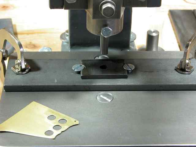
![]() My
method of making my tooling differs from John's in several ways. I like
to use bolts for my tool shanks,
instead of making them using machine collars and 1" shafting as John
suggests. In the image you can see two finished tools on the clamp
plate, and one in the upper tool-holder. There is also a bolt on the
right with a big washer on it. That one is ready to be attached to a
tool by brazing. I use those big washers with all top tooling to
protect my tool holders. I find brazing to be much cleaner and
generally
stronger for most purposes. Brazing is the great forgotten method to
join
metals for most smiths. Compare the joins visible in the image made in
the top tools, and welds done to attach the machine collar to the
bolster
plate. The welded collar, although plenty strong enough for the job,
looks
pretty poor in my opinion, not that looks in tooling is all that
important, but I like clean neat tools. No doubt many smiths can make
neater welds than I can however. I should add that on the
underside of the bolster
plate is another 1" diameter machine collar
that is welded into place and fits down into a 2" diameter hole in the
clamp plate. This provides additional lateral tool shank
support, and I can tighten both set screws to lock tools in place if
needed. Now in this image
of the P-0 press, I have sweat brazed the
machine collar on to the little bolster plate. The tool that is mounted
in the plate is a veining bottom tool that I easily made from a bolt
head which I then case hardened, and the copper leaf at the left
was veined using this tool. On the right is the 3/8" upper tool holder,
and a fence bolster plate is under the ram. I welded the fence on the
bolster plate for the small press, but used flathead bolts from the
underside to mount the tool steel fence in place for the big press. I
prefer using tool steel for fences if I have it available. The hardness
and smoothness of the ground tool steel, compared to the mild steel I
will be working against it, allows the work to slide more smoothly and
easily than it will if the work and the fence have the same hardness
and surface texture. It is an unimportant point, and I would not go out
and buy expensive tool steel to use when making fences. The tool steel
fence in the P-6 image is a piece of a shear blade I found in the scrap
yard.
My
method of making my tooling differs from John's in several ways. I like
to use bolts for my tool shanks,
instead of making them using machine collars and 1" shafting as John
suggests. In the image you can see two finished tools on the clamp
plate, and one in the upper tool-holder. There is also a bolt on the
right with a big washer on it. That one is ready to be attached to a
tool by brazing. I use those big washers with all top tooling to
protect my tool holders. I find brazing to be much cleaner and
generally
stronger for most purposes. Brazing is the great forgotten method to
join
metals for most smiths. Compare the joins visible in the image made in
the top tools, and welds done to attach the machine collar to the
bolster
plate. The welded collar, although plenty strong enough for the job,
looks
pretty poor in my opinion, not that looks in tooling is all that
important, but I like clean neat tools. No doubt many smiths can make
neater welds than I can however. I should add that on the
underside of the bolster
plate is another 1" diameter machine collar
that is welded into place and fits down into a 2" diameter hole in the
clamp plate. This provides additional lateral tool shank
support, and I can tighten both set screws to lock tools in place if
needed. Now in this image
of the P-0 press, I have sweat brazed the
machine collar on to the little bolster plate. The tool that is mounted
in the plate is a veining bottom tool that I easily made from a bolt
head which I then case hardened, and the copper leaf at the left
was veined using this tool. On the right is the 3/8" upper tool holder,
and a fence bolster plate is under the ram. I welded the fence on the
bolster plate for the small press, but used flathead bolts from the
underside to mount the tool steel fence in place for the big press. I
prefer using tool steel for fences if I have it available. The hardness
and smoothness of the ground tool steel, compared to the mild steel I
will be working against it, allows the work to slide more smoothly and
easily than it will if the work and the fence have the same hardness
and surface texture. It is an unimportant point, and I would not go out
and buy expensive tool steel to use when making fences. The tool steel
fence in the P-6 image is a piece of a shear blade I found in the scrap
yard.
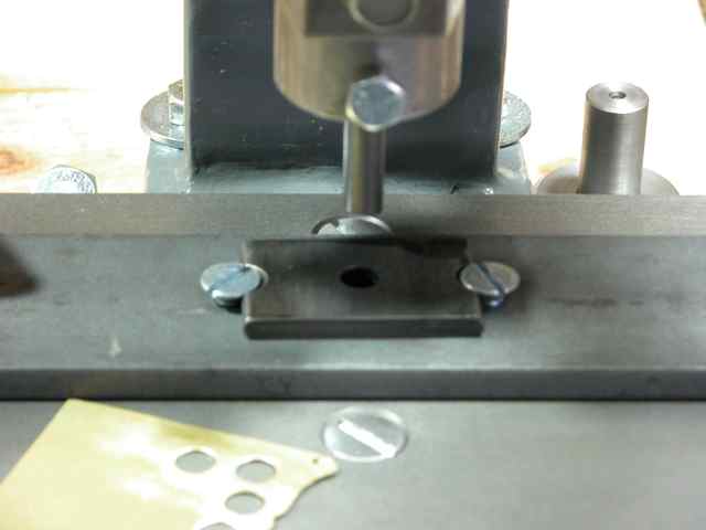
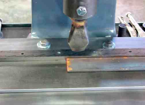
![]() In the P-0 image
I have a fence in place under the ram, and a test piece of copper on
the plate that I have edged along both edges with the fence and upper
tool you see in
the 1/2" upper tool-holder. I have upper tool-holders to hold 3/8" and
1/2"
shank tooling, and I also use 3/4" diameter tooling directly in the ram
block on occasion, but always with heavy washers, as can been seen in this image
that shows the upper offset bending tool with its washer. The washer
protects the ram block from damage. Since the P-0 tool is used for very
light work, I do not worry
about upsetting the shanks of tooling in the ram block, or damaging the
ram block, but I do round them so their end radius comes close to
matching the radius in the bottom of the ram block hole. I will not
mount any tooling directly in the 1" hole in the P-6 press ram block
because this tool is subject to much greater forces, and it works
mostly on steel, while the P-0 works mostly on copper, silver, or 20 to
22 gage mild steel sheet. Here is a
picture
of the big P-6 with its tool steel fence bolster plate in place. I have
a
very heavy duty cutting tool in the ram that can be used for edging, or
for cut-off work.
In the P-0 image
I have a fence in place under the ram, and a test piece of copper on
the plate that I have edged along both edges with the fence and upper
tool you see in
the 1/2" upper tool-holder. I have upper tool-holders to hold 3/8" and
1/2"
shank tooling, and I also use 3/4" diameter tooling directly in the ram
block on occasion, but always with heavy washers, as can been seen in this image
that shows the upper offset bending tool with its washer. The washer
protects the ram block from damage. Since the P-0 tool is used for very
light work, I do not worry
about upsetting the shanks of tooling in the ram block, or damaging the
ram block, but I do round them so their end radius comes close to
matching the radius in the bottom of the ram block hole. I will not
mount any tooling directly in the 1" hole in the P-6 press ram block
because this tool is subject to much greater forces, and it works
mostly on steel, while the P-0 works mostly on copper, silver, or 20 to
22 gage mild steel sheet. Here is a
picture
of the big P-6 with its tool steel fence bolster plate in place. I have
a
very heavy duty cutting tool in the ram that can be used for edging, or
for cut-off work.
![]() There
is one comment that you may have read on the Old World Anvils site I
disagree with. It states that you should never use hardened tool steel
shanks in your ram block, such as the grade 8 bolts I use. If the shank
never touches the bottom of the tool holder hole in the ram block, the
force will be taken by the bolt head and washer. Or if you use a
"false" tool holder,
as is shown on the right of the front bolster plate in this image of my
P-0 press, the kind of steel
the shank of your tools are made of has
no effect on the ram block. So I recommend you use any kind of bolt of
the right diameter that you find in your scrap yard. I cut the threaded
portion off using a 14" abrasive cut-off saw, grind the flat of the
head smooth, and sweat braze my tool bits into place. If you make a
little bridge, like a piece of channel with the flat side upward, put a
hole in it to put the bolt shank into so that the bolt is kept head
upward and steady, you can then put the bit on top, with your brazing
brass and flux between them, and just slip it into your forge and fire
it up to make the braze. I like to put it into a cold forge so that I
can place it very carefully into place with my bare hands. That
prevents vibration from moving the bit out of place. Once it is in the
forge, just fire it up and sit back and watch until the bit settles on
to the bolt head, turn off the forge and let it cool off. You can
harden tooling edges using a torch, without heating the braze enough to
soften it. Do not quench the hot tool after brazing
as you remove it from the forge. Use the torch and harden the edge in a
separate operation. Differentially hardened tools are far superior to
tools that are fully hard throughout.
There
is one comment that you may have read on the Old World Anvils site I
disagree with. It states that you should never use hardened tool steel
shanks in your ram block, such as the grade 8 bolts I use. If the shank
never touches the bottom of the tool holder hole in the ram block, the
force will be taken by the bolt head and washer. Or if you use a
"false" tool holder,
as is shown on the right of the front bolster plate in this image of my
P-0 press, the kind of steel
the shank of your tools are made of has
no effect on the ram block. So I recommend you use any kind of bolt of
the right diameter that you find in your scrap yard. I cut the threaded
portion off using a 14" abrasive cut-off saw, grind the flat of the
head smooth, and sweat braze my tool bits into place. If you make a
little bridge, like a piece of channel with the flat side upward, put a
hole in it to put the bolt shank into so that the bolt is kept head
upward and steady, you can then put the bit on top, with your brazing
brass and flux between them, and just slip it into your forge and fire
it up to make the braze. I like to put it into a cold forge so that I
can place it very carefully into place with my bare hands. That
prevents vibration from moving the bit out of place. Once it is in the
forge, just fire it up and sit back and watch until the bit settles on
to the bolt head, turn off the forge and let it cool off. You can
harden tooling edges using a torch, without heating the braze enough to
soften it. Do not quench the hot tool after brazing
as you remove it from the forge. Use the torch and harden the edge in a
separate operation. Differentially hardened tools are far superior to
tools that are fully hard throughout.
![]() That
is about all I have for this update. I do have a large collection of
tooling now for my P-6 press, but for the most part it is little
different from the tooling that John shows, or that most guys build.
The main concepts I wanted to suggest to you in the above paragraphs
are
to use brazing instead of welding, use bolt shanks instead of making
your own much weaker tool shanks with a collar and 1" shafting, and
using machine collars for your bolster plate mounting hardware. I think
for most purposes you will find this method easier to do, cleaner to
look at, and stronger in use, than what you can do by welding around
the edge. In use, either one is probably plenty strong enough to do the
job. I
just think brazing is cleaner and easier to do, and probably less
expensive too if done in the forge. Also, with brazing you do not get
any distortion or pulling of the metal as occurs with welding.
That
is about all I have for this update. I do have a large collection of
tooling now for my P-6 press, but for the most part it is little
different from the tooling that John shows, or that most guys build.
The main concepts I wanted to suggest to you in the above paragraphs
are
to use brazing instead of welding, use bolt shanks instead of making
your own much weaker tool shanks with a collar and 1" shafting, and
using machine collars for your bolster plate mounting hardware. I think
for most purposes you will find this method easier to do, cleaner to
look at, and stronger in use, than what you can do by welding around
the edge. In use, either one is probably plenty strong enough to do the
job. I
just think brazing is cleaner and easier to do, and probably less
expensive too if done in the forge. Also, with brazing you do not get
any distortion or pulling of the metal as occurs with welding.
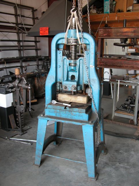
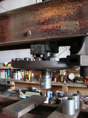
![]() Through
a bit of extremely good luck, I came across a Hopkins #2 fly-press
that is in mint condition. It was in a back room at Old World Anvils,
and after a few emails and phone calls I made an offer and it is now
here in my shop in Idaho.
Through
a bit of extremely good luck, I came across a Hopkins #2 fly-press
that is in mint condition. It was in a back room at Old World Anvils,
and after a few emails and phone calls I made an offer and it is now
here in my shop in Idaho.
![]() This
is a monster press, and one that I don't need to worry about
over-stressing the frame on. It is an H-frame press, which is not as
convenient as a C-frame, but it is immensely strong. Since this press
will not be used very often, and only for really heavy work, the
H-frame design should not be a problem.
This
is a monster press, and one that I don't need to worry about
over-stressing the frame on. It is an H-frame press, which is not as
convenient as a C-frame, but it is immensely strong. Since this press
will not be used very often, and only for really heavy work, the
H-frame design should not be a problem.
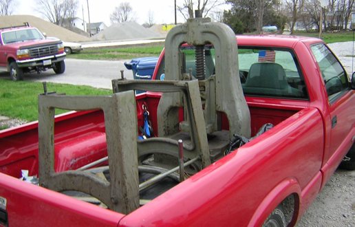
![]() Here
is a picture of the #2 Hopkins press belonging to my friend Bob. It was
taken the day he brought his Hopkins #2 press home a number of years
ago. Yes, the
pick-up was loaded to the max.
Here
is a picture of the #2 Hopkins press belonging to my friend Bob. It was
taken the day he brought his Hopkins #2 press home a number of years
ago. Yes, the
pick-up was loaded to the max.
Some of My
Other Metalwork Related Pages
The Full Site Map - Lists All Pages on This Site
Page By: Ron Reil
©Golden Age Forge
17 Sept 07