

(Image by permission from "The Plaza del Herrero"
in Ecuador.)
"Golden
Age Forge"
Welcome
Friends!
"Foundry" spoken here too.

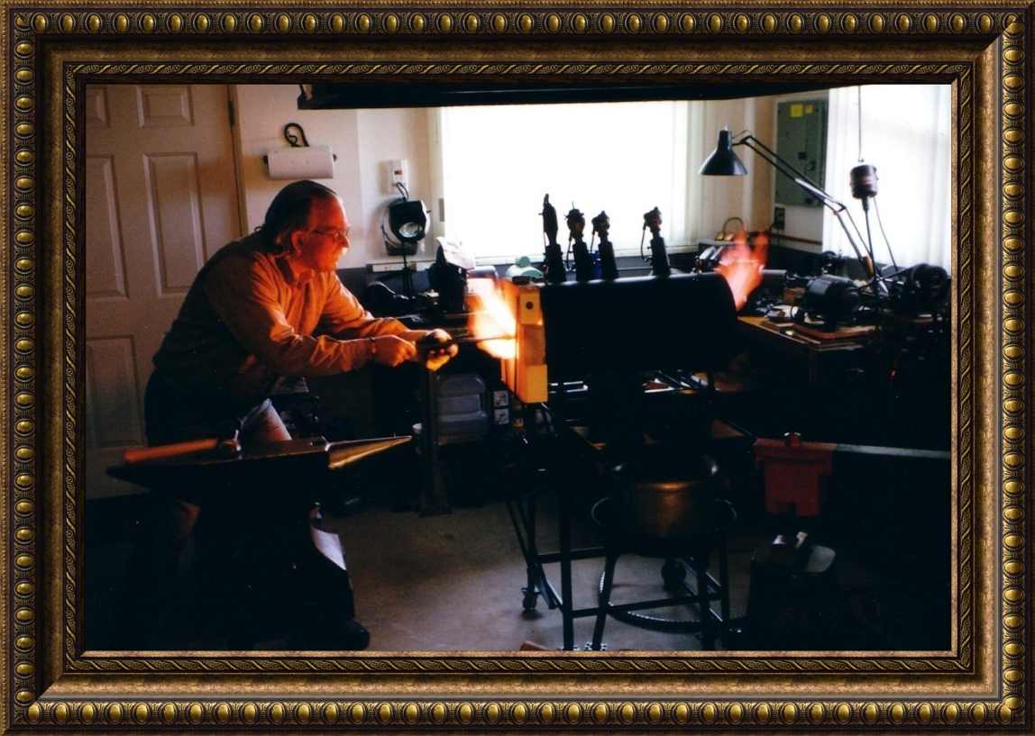
I am about to forge-weld a Spontoon pipe-axe head. Click on image for full size.
(This excellent picture was taken by my
apprentice, Kevin Brown.)
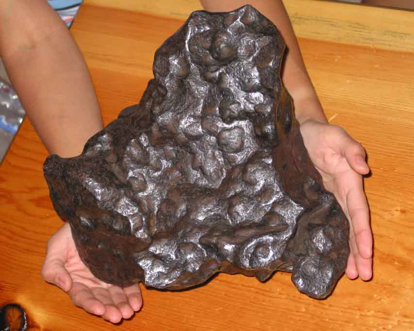
An
Addition to My Shop - Out of this world!
This is a 64 pound nickle-iron meteorite from Argentina that
fell about 4000 years ago!

Warning!
 I provide the following
information as a service to the blacksmithing community. Although the
designs I employ in building my burners and forges are safe and
reliable in the way that I use them, the same may not be the case for
you. You assume all risk in using this information, or any
other information on this page. Other designs that I may have
posted here, or on my other pages, have been submitted by
other smiths, and I have no experience with most of them. Use care and
good sense in using any of these designs. Get help from a knowledgeable
smith if you are new to this work. Don't take chances because these
tools can cause injury, blindness, or even death, if used improperly.
Also, be sure you are in a well ventilated space (see the Nighthawk CO
& explosive gas detector paragraph), or better yet,
work outside. Additionally, never operate a forge that is
connected directly to a propane tank that is near a forge, or indoors.
An emergency pressure valve release could instantly place you in the
middle of a fireball. Follow all local codes regarding
indoor use of propane, and I believe indoor use of a propane
tank violates code everywhere in North America, and most of Europe. A
new concern has arisen with the introduction of the "Mongo Burner
Series." Please read carefully all the information in the separate "Safety Warnings and
Considerations" information which heads the "Mongo Burner
Series" section. Thank you.
I provide the following
information as a service to the blacksmithing community. Although the
designs I employ in building my burners and forges are safe and
reliable in the way that I use them, the same may not be the case for
you. You assume all risk in using this information, or any
other information on this page. Other designs that I may have
posted here, or on my other pages, have been submitted by
other smiths, and I have no experience with most of them. Use care and
good sense in using any of these designs. Get help from a knowledgeable
smith if you are new to this work. Don't take chances because these
tools can cause injury, blindness, or even death, if used improperly.
Also, be sure you are in a well ventilated space (see the Nighthawk CO
& explosive gas detector paragraph), or better yet,
work outside. Additionally, never operate a forge that is
connected directly to a propane tank that is near a forge, or indoors.
An emergency pressure valve release could instantly place you in the
middle of a fireball. Follow all local codes regarding
indoor use of propane, and I believe indoor use of a propane
tank violates code everywhere in North America, and most of Europe. A
new concern has arisen with the introduction of the "Mongo Burner
Series." Please read carefully all the information in the separate "Safety Warnings and
Considerations" information which heads the "Mongo Burner
Series" section. Thank you.
An additional item that should
be of interest to you is obtaining an explosive gas/CO
detector for your working space. Mark Manley, of "Manley
Metal Works," Silverton, Oregon, provided a short piece of very
important information in the Winter 2000 issue of "Hot Iron News" that
I feel needs to be passed on to a wider audience. There is a very
reasonably priced digital read-out combination explosive gas and CO
detector available in local hardware, building supply, and other
stores. I was concerned about having a CO monitor in my shop, even
though I have a very efficient induced draft hood in my shop. The
detector is made by "Kidde Safety," and is called
the "Nighthawk." I will not go into the specs for
the instrument here, it is available on the Internet if you look up
"Kidde Safety," but I will say that it is a very finely
designed and built instrument. It runs on 110 VAC, and has a 12 VDC
back-up. It plugs directly into an outlet, or the transformer plug
detaches for remote mounting up to 6' from the plug. You can easily
check your CO level with a quick glance at the digital read-out. If it
detects any kind of flammable gas it will instantly sound a very loud
audible alarm, and the word "Gas" will display on the digital display.
If it detects CO it will sound a different audible alarm and display
the PPM level of the gas. Also, you will know it's operating because
the blinking decimal point in the digital read-out indicates it's
operating and sampling the air in your shop.
I bought one of
these instruments for my shop, and I was so impressed with it that I
went down and bought a second one for my home, which has natural gas
heat, gas hot water, and a natural gas fireplace insert. I priced CO
detectors on the McMaster-Carr web site, and CO detectors alone were
$170, where this combination instrument is only $59 at my local Home
Depot. Considering how deadly CO can be, this instrument is very
inexpensive, and well worth the investment. It may well save
your life. After Mark installed his "Nighthawk," he discovered that he
had been exposing himself to CO levels of 30-160 PPM while running his
forge! Thanks for the tip Mark.
Note:
There has been a recall of Kidde Safety "Nighthawk" gas and
CO detectors. This does not affect any detectors sold after the date
that I posted the above information, however you may check your unit by
going to http://www.cpsc.gov/cpscpub/prerel/prhtml99/99082.html.
A Word About Obtaining My Help
I am no longer
able to offer my support to help solve problems you may have with your
burners or forge. I have reached the point that something has to give.
Two to three hours a night answering questions has brought my metal
working each evening of the week to a stand still. I will continue to
update my blacksmithing pages, and may now also have the time to clean
out some of the outdated and conflicting information in my pages,
however, I will no longer be able to troubleshoot your system. If you
build your burner to the design specs and information shown and
discussed on my pages, including in the Troubleshooting Document and
FAQ, your burner should work well. If it doesn't, then its not built
correctly, and you will need to make some adjustments after looking
through the available information. The best thing to look at when fine
tuning your burner are the various flame images I have
posted. If yours looks like these images, you probably have it right.
Here are a few helpful links.
FAQ
Forge & Burner
Troubleshooting Document
Some Often
Asked Questions
EZ-Burner
Construction
Rich To
Lean Flame Image
1) T-Rex Flame
Image - Ideal Neutral Flame
2) Side-arm
Burner Flame Using Temporary Cast Iron Test Nozzle - Slightly Reducing
Flame
3) Another
Flame Image - Oxidizing Flame
The bottom three
flame images give you views of burner flames adjusted to 1) neutral, 2)
slightly reducing, and 3) strongly oxidizing. The burners have nothing
to do with it, just the choke settings. All of these images could have
been done with the T-Rex, or Side-arm burners. At your high end gas
pressure, if you have achieved a flame similar to the oxidizing flame
shown in the bottom image, #3, you will then have full control over the
burner flame across the full pressure range. This will allow you to
achieve oxidizing, neutral, or reducing, flames as needed by simply
adjusting the choke. You will then have a properly functioning burner.
Links Local to My Site
The Full Site Map - Lists All Pages
on This Site
Golden Age Forge Gallery
All Three Volumes
of "Best of Theforge" Zipped - (257K)
-or-
The Best of Theforge -
Vol 1
The Best of
Theforge - Vol 2
The Best of
Theforge - Vol 3
Subject
Index for This Page
Safety Warning
Additional Forge and Burner
Design Information
My Shop is Born
My Open Air Smithy
My Blacksmithing Background
& Big Coal
Forge
Jet Pump Motor 12" Disk Grinder
My 4-Burner Forge
Idle/Full Valve Arrangement
The Reil Burner
The "T-Rex" Burner Series
 Ribbon Burner
The Restoration of My Little Giant
Easy Hammer
An Update
Some Useful Tools
-Iron Wheel
Carousel Tongs Rack
-Double Reversed
Twisting Jig
-Torch Cart
-Universal
Position Welding Jig
Table
Some Blacksmithing and Foundry
Links
New Arrival, A Swarm
Closing
Forge and Burner Design
Information
This
page has information
about several of my coal and gas forges, and the "Reil and EZ-Burners,"
but
most of the forge and burner design information can be found on my
other
page, the Forge and Burner Design
Page. Please
visit my other page if you are in need of further information. I should
add
that you should check out the "Mongo
Burner,"
and the smaller versions of this burner, as well as the
T-Rex and
Shorty
burners, before you settle
on a burner design to build for your own forge or melting furnace. This
information is on my other page, along with a huge volume of other
information
related to this topic. Do explore this present page first however,
because
it does have a lot of information of value that is not found
on my other
pages. Thank you.
The
Construction of My New Smithy
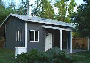
Shop on 26 June 01
(Click thumbnail to go to my Shop Construction Page.)
I
decided that
this narrative was becoming too long to keep on this page. I have
created
a separate page dedicated to the construction of the shop where I can
include
more detailed information and more images. Please visit my
"Shop Construction Page" if
you are interested in
the special features my "smithy" has incorporated into it. Thank you.
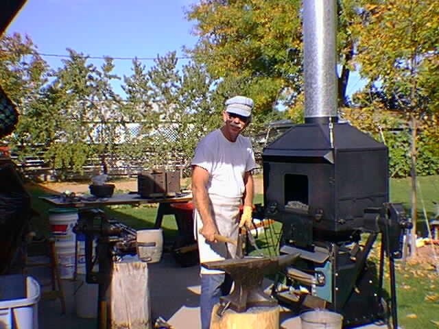
My
Old Open Air
Smithy/Foundry

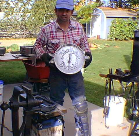
Working at my coal forge
(Click image for enlarged view)
In the background
of the above picture you can see a foundry pour Blaine and I have just
finished.
It is on the table cooling. It is an aluminum Dutch oven lid with a
special
name cast into it. It was a Christmas gift for one of Blaine's friends.
If
you will click here you
can see Blaine holding the
results of our efforts. I think it was worth the work. For a close-up
of
the casting click here.
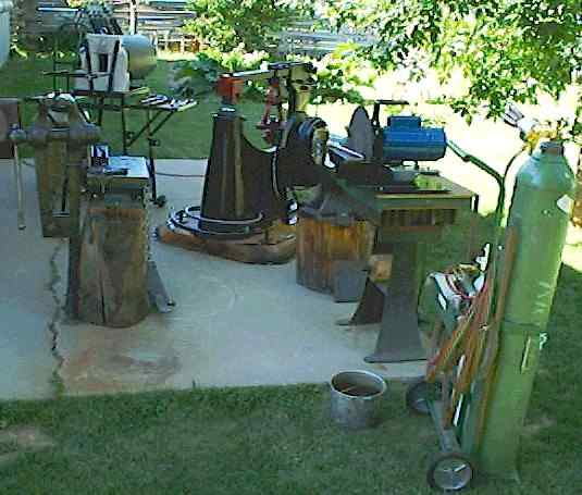
What you see in
the image is what I used to have to call my "smithy." I am elated to
report
that I am now working out of a very fine shop building, shown above,
and
no longer have to be an armchair smith in the winters. :-)

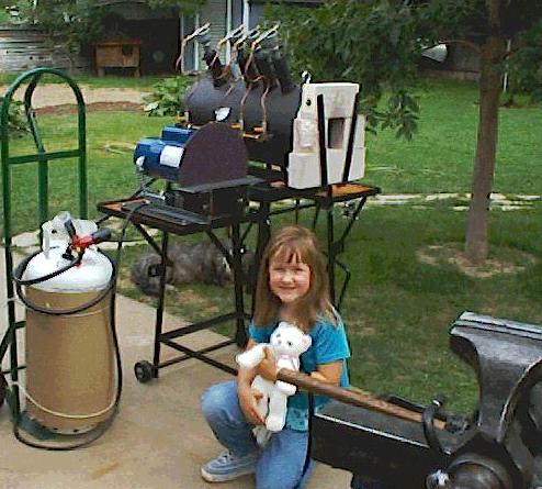
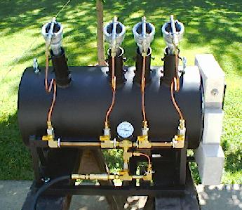
My big gas forge,
daughter Natalie, and 12" disk
grinder
This
is my main work-horse
forge. The burner arrangement allows me to run three burners equally
spaced,
close together, or three burners equally spaced, and farther apart. I
never
run all four at one time, and normally only use one burner. The forge
has
an interior movable back wall, and an "idle/full valve arrangement
which
is hidden behind the grinder. The cart has two swing-up side tables,
and
a swing-up, adjustable, work support bracket
(Image1, Image2) in
front....a very useful addition to a basic forge. The cart allows easy
movement
of the forge by inserting two "wheelbarrow" type handles into the side
brackets
provided. Here is another image showing my entire
"smithy" setup as it is in
the summer, but all of
which will soon be in my new shop.
My
four burner propane forge
is going on its 5th year of use, and its interior is still in very good
condition. The floor is a little messed up near the front from welding
flux,
but I quickly learned to use a 1/2" thick "slick" made from a kiln
shelf
to protect it when doing forge welding. Barring accident, I would
expect
to get another 5 years or more out of the lining without any problems,
perhaps
considerably more. Since building this forge I have not even moved my
big
coal forge out for use even once, although I have fired up my small
open
pan coal forge on several occasions for items that would not fit in the
chamber
of my gas forge. The gas forge is a joy to use due to its almost
instant
heat and incredible economy of operation. Use of the coal forges will
probably
end completely when I have complete construction of the
Clam-shell forge.
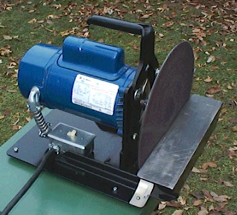
I
made my 12" disk grinder
from a new 3250 rpm,
1-1/2 hp, jet pump motor, and used a precision backing plate made by
"Shopsmith",
which was also new.
It has a 5/8" motor shaft hole, and the platen is about 1/8"
thick.
It is not keyed to the shaft, just has a large set screw, so you need
to
have a 5/8" motor shaft with a flat side, or file one on it. I actually
filed
a rounded notch in the shaft, instead of a flat, to engage the set
screw
in order to make it more secure from loosening and sliding on the
shaft.
The platen is very precision made, and of high strength steel. When I
turned
it on for the first time I was amazed to see it rotate with virtually
no
wobble at all...perfectly flat running. I forged the handle from
a 3/8"
x 2" steel bar which I split lengthwise, and then punched and
shaped
to allow it to be attached directly by using the motor mounting bolts.
I
think that this 3/8" thick forging would be very difficult to make if
you
do not have a swage block. It is not easy even with a swage block.
Notice
the back end of the handle, which has a down dropped and rounded
partial
flange to prevent it sliding out of the hand. The handle is rock solid
and
secure in use. (Note:
The "Shopsmith" disk grinder
platen comes with a warning label stating not to spin it faster than
2000
rpm. I do not recommend you do so, as I am doing, unless you do your
own
engineering design calculations to determine if the steel
platen can
be rotated safely at the higher speed. I make no suggestion that it is
safe
to do so. If you decide to spin it at a higher than recommended speed, you
do so entirely at your own
risk.)
My Blacksmithing History, and My Forge
My interest
in blacksmith work started early in life when I lived in Okinawa. I
built
my first small "beehive" forge from clay, and was able to get metal hot
enough
to do some simple forging operations with it. I was only about 13 years
old
at the time. When I was 16, I built a bottom blown furnace which a
friend
and I used to melt iron to cast a simple cannon. The cannon was a grand
success,
capable of shooting through 16 inches of Madrona tree in my back yard!
My
father was not impressed.
Following the cannon
episode, my "talents" were to lay hidden for many years until a good
friend
asked me if I wanted to help him build a simple
forge
to heat treat a large block of steel
with. I thought
it sounded interesting, and so started an epic that culminated in the
construction of the forge you see in the picture at the top of this
page,
and eventually with the construction of my blacksmith
shop. The construction of the forge took seven years on a
weekend, part
time, basis, but the results were worth all of it. The forge has an
expandable tuyere enabling
me to maintain a fire in
a small radius, or lengthen the tuyere to as much as 17 inches for
large
heats. The tuyere block is almost three inches thick, so no matter how
hot
the fire, or how long I maintain it, the tuyere never gets hot enough
to
burn.
Inside the forge
there is a swing arm crane for handling lead pots, or brass melting
ladles.
The forge has a hand cranked blower,
and an electric
blower with an air dump
to vary the blast when
using the powered blower. Also, the bed of the forge is fully
lined with fire brick, so
even after a full day of
operation you can still place your hand on the outside with little
discomfort.
The only down side of this design is the lack of a clinker breaker. To
have
the variable tuyere I had to give up that convenience. That means that
I
have to open up the fire periodically to lift out the clinker and clear
the
air holes. If my timing is good, the clinker will lift out all in one
big
piece, making the operation quick and clean. It doesn't always work
that
way however.
The forge pan is
constructed out of 1/4 inch steel plate which I lined
with
fire brick when the metalwork of the forge was complete.
Following completion
of the basic forge, I used
the unit for several years
until I found that the smoke was having an adverse affect on my health.
I
decided to construct a hood that would protect me from the worst of the
smoke.
The first version had an 8 inch diameter chimney, which was not big
enough
to handle the heavier smoke during some start-ups. So, I cut out the
thimble
and fabricated one 10 inch in diameter, and the chimney finally worked
perfectly.
If you would like to see a high resolution image of the finished forge,
please
click here.
While I was building
the forge, I was also building an "anvil work station." It evolved into
an
anvil block welded on a heavy steel plate "work surface," i.e. small
table.
I also built a hold fast, or third hand, to help me work alone. I later
lucked
into finding several very nice anvils, one of which you can see in the
picture. In the process I
also collected a lot of
other equipment, including five excellent post vises
(including a pristine 8" Colombian post
vise), two brand
new pairs of blacksmith's shears,
a fine
post drill, and numerous
other odds and ends. I have
continued to build some of the many tools needed in this work, with a
goal
of eventually spending my time in decorative iron work.
The project was far
more successful than I ever expected it to be. I have used the forge
for
my foundry work, easily melting large crucibles of aluminum. I have
also
taken heats on several large pieces of iron weighing 100 pounds or
more,
with no problems encountered, other than those related to the handling
of
massive blocks of red hot metal.
I have now had the
time to get into some very fine metal work, and the future looks very
bright.
This "hobby" has now evolved into a small business, and its growing
rapidly.
I still have a ways to go before I am showing a net positive cash
balance,
based on what I have put into my shop and tools, but that
point is getting
closer every day.
I was very lucky
several years ago to find a large amount of old "wrought iron", some of
it
in massive sections, at some of our old Idaho mining sites. I collected
as
much as I could, and am still finding more on occasion. I want to use
this
hundred year old iron for projects that would be of special interest to
people.
So far, about all I have made out of it is a series of leaves for key
chains.
They were received warmly, and are still being used by many of my
friends.
I don't know if it is the workmanship or the historical interest of the
metal
that has made them successful.
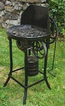
Besides my big coal
forge, I have another small open pan riveter's
forge
that is in excellent condition, and that I have restored to look brand
new
for demonstration forge work. I also have completed the building of a
four
burner propane forge that will allow almost "instant on" forging with
its
Kaowool liner and reflective coating of ITC-100. The convenience of
having
an "instant on" forge fire is wonderful for short forge sessions in the
evening.
Being a 24" long cylindrical forge, it also allows me to heat much
longer
sections of iron uniformly than was possible for me in the past. This
is
more of a bladesmith's forge, and its ability to easily forge weld is a
very
welcome addition. Gas forge welding is far easier than coal forge
welding.
As I mentioned above,
I now have an 8" Colombian post vise.
I obtained it
as a result of a contact I made at the Sumpter flea market in Oregon. I
also
obtained a fine post drill
for $20 from the same fellow!
After cleaning it up I fitted it with a new 1/2" chuck, and it has
become
one of my most appreciated tools. I was amazed at how efficient the
drill
is. It can easily push a half inch bit through 1/4" plate in a minute
or
so, without a pilot hole! The post drill still has the original paint,
and
apparently had never been used, as the quill has no play at all.
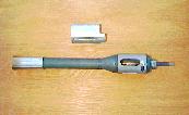
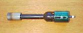
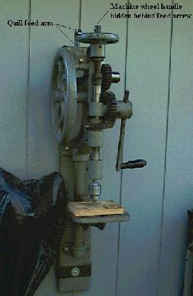
Another
post drill came into my shop that is even more surprising. It
is in superb
condition, no slop in the bearings, has a fine new "Ridgid" three jaw
chuck,
and even has the original paint on the black wooden handle. On top of
all
that it is a large one, fully twice as big as the above mentioned
drill,
has two speeds, and drills a half inch hole effortlessly. A friend
offered
it to me for $25, and of course I grabbed it. It had one defect, it had
the
quill advance arm broken off, and the part that engages the top ratchet
quill
advance wheel was missing. Luckily the lower half that rides the cam
was
still present. I forged the missing part, which involved making a split
fork
mounting bracket for the little ratchet pawl that engages the ratchet
wheel,
and after brazing it in place and painting it, the part looks
completely
original and works perfectly. It is now my main drill. The image
indicates
the part that I had to rebuild. Once in a while things come along when
you
are least expecting them. :-)
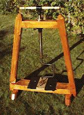
Another
drill press that may be of
interest is one that I built,
which is patterned after an early 1800's press that uses a large ACME
screw
to apply crowd pressure to a heavy forged brace. The press uses spade
bits,
which I forge myself. Although not a speedy operation, it is a very
easy
drill to use, and can easily drill 1/2" to 1" holes through heavy
plate.
I was really amazed the first time that I used the press how easily it
operated.
I also quickly learned that the angles on the spade bits are very
critical
or they will drill triangular holes instead of round. I later lucked
into
finding a second perfect hand forged brace at the Sumpter flea market
for
$1 that is much heavier than the one I forged. It displays no flexure
in
use, even when very heavy crowd force is applied with the ACME screw
feed.
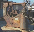
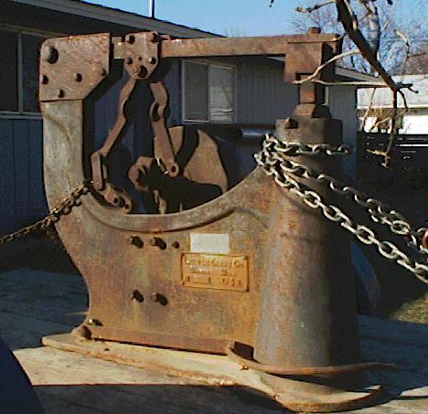
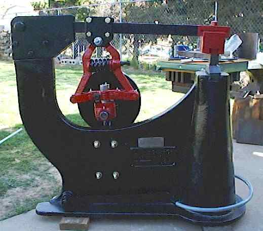
The gentleman I bought
the smaller post drill, and a 4" post vise, from mentioned that he had
a
big post vise at his ranch in
Washington. I was
interested, so we exchanged information. A few days later he contacted
me,
and I arranged to come up and have a look at it. After a 325 mile drive
I
arrived at his ranch to a warm welcome. After coffee and cookies, he
took
me out to show me the vise. At first the heavy coating of mud and horse
dung
concealed the condition of the vise underneath. After a little
investigation
I bought it, and returned the 325 miles to my home in Boise. It was not
until
several days later that I cleaned it up and discovered what a treasure
I
had come upon. It is now all cleaned up, and gleams in a coating of
oil,
waiting to be mounted. I feel extremely lucky to have obtained such a
massive
vise in such excellent condition. The jaws do not even have any hammer
marks
on them. Apparently it is virtually brand new and unused, and just sat
in
the old barn for the last 100 years or so. BTW, the little girl next to
the
vise in the image is my daughter Natalie when she was 4 years old.
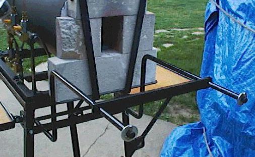
My 4-Burner Propane Forge Design
I have completed
the construction of a propane forge
using the burners
described in the next section below. It utilizes 4 burners in an
asymmetric
burner arrangement. It also has an easily movable "Kaowool board" back
wall
that allows for instant adjustment of the length of the forge chamber
to
achieve the highest temperatures possible for the given work placed
into
the forge. This is a naturally aspirated forge, no blowers, that easily
reaches
welding temperatures, and above, and I am at an elevation of 2300 feet.
Additional
Image #1
Additional
Image #2
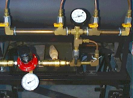
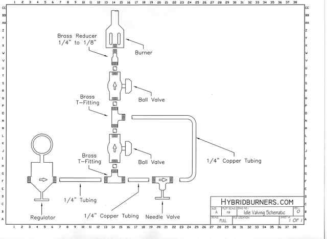
Close-up
of Idle/Full Valve Arrangement
or
Idle/Full Schematic
Diagram
For a far more
economical forge, you should use an "idle/full" valve arrangement so
that you can instantly drop your forge to a quiet idle when you are at
the anvil, or tending to some other chore, such as a phone call, etc.
When you return to the forge, a simple quarter turn of the lower ball
valve instantly brings the forge back up to full heat. You will
discover that the forge will not lose its operating temperature when in
idle mode either. The idle/full schematic
diagram is self explanatory, and you can easily figure out
how to adjust the upper and lower gas pressures by using the needle
valve and regulator for your particular needs when starting your day at
the forge. Although the schematic calls for 1/8" plumbing, you may want
to use 3/8" for everything except the little bypass that has the needle
valve in it. If you are using more then one burner, the larger diameter
plumbing will provide a better fuel flow with less pressure drop.
(Thanks goes to Rex Price of Hybridburners.com
for the excellent Idle/Full schematic diagram.)
The forge uses 2"
of Kaowool coated with
ITC-100
"black body
radiator" ceramic coating material made by
"International Technical Ceramics Corporation." This material radiates
98% of all the IR that it absorbs
back to the work. This creates a hotter and more economical running
forge
with a cooler shell.
The floor of the
forge consists of a half of a 1" thick, high alumina, kiln shelf
supported
on six kiln shelf posts, each 1" long. The hollow kiln shelf posts are
held
in place by 3/8" diameter by 1/2" steel pins blind welded into the
forge
shell. The posts sit over the pins. With this arrangement a full
circumference
1" layer of Kaowool can be installed which runs right under the floor
plate,
thus increasing the insulation and efficiency of the system. A second
layer
of Kaowool runs from one side of the floor plate up and around to the
other
side.
The front
opening of the forge is closed with special ultra light weight, high
"R",
fire-bricks. I have a brick shelf constructed which the bricks rest on.
To
prevent accidentally snagging a brick off the shelf while removing work
from
the forge I have two additional spring keeper rods that hold the bricks
to
the face of the forge. The bricks can be moved to adjust the opening as
required
by different sized work pieces. With the movable back wall, and
adjustable
brick front end, the forge has very great versatility in its use and
configuration.
If you have additional
questions after viewing the burner drawing and document below, please
feel
free to e-mail me with them. I would be more than glad to help you with
any
questions, or in helping you design your own forge, propane or coal.
Update:
I made two important changes to my big gas forge that should be of
interest
if you want to build one. I retrofitted two of my burners, #1 &
#2, to
the Bordeaux modification, and additionally used a new method to lock
the
jet tube which requires no drilling or tapping of holes. I also added
an
axial choke to these burners at the same time. This first
image shows the details of the burner modification, and the
second image shows both
burners in place and in
use, and also allows comparison to my old burner style on burners 3 and
4.
For more details of this burner modification please go to my
burner design page and
look under "Chokes".
The other change
was to my movable back wall and is of equal importance and utility. I
cut
a small, 1-1/2" wide by 1-1/2" high, opening in the bottom center of
the
Kaowool board at floor level to allow long work to pass though the
wall.
The opening tapers inwards, losing about 1/2" of its width at the top
of
the opening. To do this I had to fabricate new stainless steel supports
to
keep the back wall vertical but allowing clearance for the opening.
This
allows the wall to be moved forward to create a very small chamber
volume,
heating only a small portion of an otherwise long item, and
preventing
scale formation on those portions not heated. In the past I
had to
move the back wall back for long work, which heated the entire object,
even
if I only had to actually work a small section in its center. I made
this
change so that I could obtain better finishes on things like these
snakes, made from railroad
spikes...also
shown.
One additional
operating tip, for multiple burner forges, that you need to be aware of
regards
how to handle the individual burners while the forge is running. If you
leave
the burners open, and use only one or two, the others will act like
chimneys
and quickly become extremely hot, damaging them. You only have to stuff
a
small wad of paper towel into the throat of any unused burners to
prevent
this, and when you wish to add a burner, just pull the paper out with a
set
of needle nose pliers, and immediately open the gas valve for that
burner.
You do not need to shut down the forge to add or remove burners from
operation
while the forge is running. The heat in the forge will not even scorch
the
paper most of the time, although it will do so to a limited degree when
placing
the paper into the burner throat when the forge is running due to the
chimney
effect. Of course this technique only works if each burner has its own
individual
valve, a requirement in my opinion, if for no other reason than fuel
economy.
Originally
my four burner
asymmetric layout was intended to allow three equally spaced burners to
be
used close together, or three burners equally spaced but farther apart.
After
switching over to T-Rex burners I found that four burners are too many
for
the 24" length of the forge. I recommend you use only two or three
burners,
and a 14" diameter shell, so that you can install three inches of
Kaowool.
With three burners you can sill set them up to run two or three burners
equally
spaced, but never run all three at one time. I will be changing my
forge
over to use a 14" shell and three burners soon. Even
if you are
using Reil or EZ-Burners, use only two or three burners. The only time
I
can see that anyone might want to run all three burners at one time
would
be for bringing a long length of iron up to forge welding temperature
over
its full length. This may be of use when producing Damascus billets
employing
the "new" rolling method.
You
may also be interested in my single burner "Freon
Tank Mini-Forge." This little forge has been a very useful
addition to
my tools, and may be something that would be useful to you too.
Some Propane Burner Designs
"The Reil Burner"
I strongly suggest you read the "Side-arm Burner" note at the bottom of this section
before deciding on a burner to build. It is the design I now recommend
for the guy who wants to build his own burner.
I have posted a
design modification to the
well known "Russ Vullo/Derry
Cook" propane burner (Aussie Burner) design that may interest you if
you
are going to build a forge. This burner will sustain an open air flame
with
input propane gas pressure as high as 54 psi! At that pressure the
flame
is blue for only 1-1/2", indicating an almost total burn at that point.
It
is a big jump forward from the older design. I also have a
FAQ available that
discusses the details for
constructing the burner, as well as details of the regulator and other
related
equipment. There is also a section included on tuning the burner, even
though
the information is available elsewhere. You are welcome to share this
information, but please leave all credits on the documents, both mine,
and
the ones for those smiths who did earlier work to help develop this
burner
in the past. They deserve credit too. Thank you.
Note: Brian Boorman
has created an outstanding step by step pictorial web page showing the
complete
construction of a Reil Burner. If the line drawing linked above isn't
enough
information for you to work from, you may want to visit Brian's page.
Go
to
http://metalcast.boorman.us and
click the "Propane Burner" link. I want to thank Brian for his
outstanding
contribution to the metalworking community.
NOTE:
I have now included
an additional "EZ-Burner"
design that you may
find much easier to build. It eliminates the difficulty of doing the
flare
in the nozzle, and also eliminates three of the drilled and tapped
holes.
I am not including a drawing for this modification as it is not
necessary,
but I do have a burner image
that may be of use.
The "EZ-Burner" HTML document linked above should provide all the
information
you need to build this quick and easy burner. It should only require a
couple
of hours to complete it.... I would like to include one additional note
about
galvanized pipe. By all means do use it for your burner. It will not
get
hot enough to bother the galvanizing, except for the last 1-2 inches,
and
if it does, you are doing something wrong. Properly used, the burner
should
be cool enough to handle at all times, except for the 1" diameter
nozzle
piece at the end. The galvanizing will protect your burner from rust.
If
it does get hot enough at the end to burn off the coating, the tiny
amount
involved will not cause you any problems, and its a one time event.
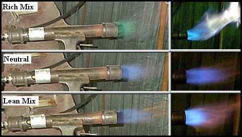
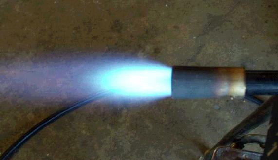
I have recently
added a very valuable image
which shows
how to judge your burner flame to determine if its running lean
(oxidizing),
neutral (best setting), or rich (safe for the iron but wastes fuel, is
low
in temperature, and can create a CO hazard). Credit goes to
Rupert Wenig for taking the series of images of
his Minimongo
Burner that I was able to assemble into this very useful composite
image.
The only thing that varies from image to image is the choke setting.
The
gas pressure was set at 10 psi for all images.
A suggestion that I
highly recommend to you is to use a 14T
Tweco
tip on your "Reil or EZ-Burner" jet tube, instead of just
drilling the
jet opening in the jet pipe wall. This tapered copper tip will produce
a
superior intake vacuum which will result in a much greater burner
output.
If you do decide to go this route, you should use a 2" diameter intake
bell,
instead of the smaller one, to allow it to draw in the additional
volume
of air it will require. You will also need to use a larger jet diameter
to
allow more gas to be injected into the burner, balancing the additional
air
intake, or it will run too lean. If you elect to use this
modification
please read the warning
section at the
top of the "Mongo Burner" section of my Design Page.
Here is a very
cleaver way to mount your axial
choke. You may
need to increase the bell to 2" diameter however in order to compensate
for
the additional obstructions in the throat of the bell. Mr. Bill has
eliminated
the additional short nipple and mounted the axial choke right in the
cast
iron bell. Contact "Mr.
Bill" if you
have any questions.
Note:
There is now a burner design you can
build more easily than either the Reil or EZ burners. The Side-arm
burner design has now been perfected, and I recommend it. It can't
match
the output and range of the impressive T-Rex family of burners shown
below,
but its still an excellent burner for any forge or furnace. I have the
latest
information and images available on my Design
Page under the Mongo burner heading. Be
sure you use the new
design that uses an enlarged intake bell....see the images I have
posted.
Premade Burners Are Now
Available
The "T-Rex" Family of Burners
There
is now a superb
new premade burner available for those who do not want to build their
own,
or for those who want the ultimate in both quality and BTU output.This
burner was selected by NASA for a secret project after they scoured the
world to find the hottest naturally aspirated propane burner available.
This
is
a turned, milled, and tuned, hybrid designed jet ejector burner
which has
to be experienced to be believed. For a complete description see the
T-Rex Burner page.
Another
burner that you may want to consider, and part of the
developing T-Rex
family of burners, is the "Shorty Burner." This is a
miniturized T-Rex, and has
applications in places
where the T-Rex may not fit, or where this reduced sized burner would
be
more convenient. I have a Shorty
Burner Page available
if you would like more information.
You
may
go directly to
Rex's own Burner
page if you wish. He has a trouble-shooting page, and a price
sheet there,
as well as a short description of the burners he presently is
producing,
which now include several much larger burners than I have listed here.
I
will not keep his full listing of burners updated on this page now that
he
has this information available for you on his page. The
descriptions
for the T-Rex and Shorty burner I have here are more complete than what
you
will find on Rex's site, so you may want to read these first, and then
link
to his site. I have links to his site at the end of each of the above
linked
pages for your convenience also.
Pine Ridge Burners' "Ribbon Burner"
This
is a new addition to my page, and is the only burner on my web site
that is not naturally aspirated. You can get this propane/natural gas
burner in a variety of lengths, from 4" square, up to 4" x 19". It is a
blown, double mixing chamber, burner that has an initial fuel/air
mixing chamber feeding the initially mixed gases through secondary
mixing jets into a second mixing/injection chamber on the back side of
the ceramic nozzle block. It achieves a very high degree of mixing,
resulting in a very efficient and complete burn. The gases then pass
through large diameter jet openings in the ceramic burner block into
the forge or furnace chamber. The only temperature limitation for this
burner system is the power of your blower. The more blower power you
have the more propane or natural gas you can feed it, and the hotter
your forge or furnace will be, surpassing forge welding temperature.
This is not an inexpensive system to set up. If you use all the various
associated air supply and safety hardware that goes with this burner
you can easily approach $1000. If you already have a high pressure
blower and other supporting safety hardware you can cut your costs
significantly. Based on base costs, and system complexity, the T-Rex
burner would be a logical choice for most smiths, but if you need
maximum BTU delivery at the highest possible temperatures, this burner
is an excellent choice.
http://www.pineridgeburner.com/

Ribbon Burner running at a low idle
An Exciting New
Tool
Click images for enlarged view.
The finished Easy Hammer on
my patio ready for
work.
Here is a view of the hammer ready to get down to business in
my
shop.
I just added a wonderful
new tool to my collection (April, 00). Actually it has taken me about 4
months
to add it, as I had to restore it first, but it is now complete. I was
very
fortunate to come into possession of a 100
year old
Little Giant "Easy" Helve Hammer. This is a very rare and
particularly
hard hitting model of power hammer. It is rated as a 35 pound
hammer,
but due to the lever arm of the helve hits with the force of a 50 pound
Little
Giant! Apparently it was stored on an Indian reservation in northern
Nevada
for the last 100 years in an unused condition. It was rusted and badly
frozen
up. At some point someone tried to run it, badly damaging one of the
frozen
bearings, but I have repaired all that now, and the
finished hammer shows the
results of my work. In
fact the main bearing that is between the two little cheek plates on
the
helve arm is now a totally new and redesigned bearing of larger
diameter.
It is now also axially lubricated with grease. I expect it
will last
far longer than me. I should add that the black foot-rest ring that
surrounds
the main treadle ring, see the finished hammer image, was made out of a
1"
diameter "wrought iron" bar, as were the short 3/4" diameter support
bars,
to be in keeping with the age of the hammer.
The hammer turns over
by hand rotation of the flywheel without any binding or noise in an
amazingly
smooth manor. It took a full day to shim everything into perfect
alignment,
but it was worth the effort. The clutch operates in a very smooth manor
as
well. I am elated at how it turned out, and expect to get many years of
service
out of it. During the restoration I converted all oil ports to Zerk
fittings,
so now the entire hammer uses grease instead of oil, that is everything
except
the clutch cones. They still need an occasional drop of bar oil. This
hammer
does not sling oil, a very nice feature in my opinion.
All parts, other than
the main hammer body and the babbitt bearings, were "derusted" using an
electrolytic rust reduction tank I put together. This resulted in a
"like
new" surface on all parts. If you look at the die blocks in the image
you
can get some idea of the quality of this process. BTW, the dies are
original
and unused! All parts were then painted with Rustoleum "Rusty Metal
Primer"
undercoating and a Rustoleum top coat as shown in the image. I have
found
this paint combination to be very long lasting.
When I assembled the
hammer I was amazed how tight all the bearings and bushings were. There
is
virtually no slop or play anywhere, and by good fortune, the only
damaged
bearing was the one I redesigned and replaced. This hammer is actually
in
much better condition now than when it left the factory a hundred years
ago.
As I mentioned above, it took me a full day to perform the alignment of
the
crank arm with the plain of the helve arm motion. This apparently had
never
been done at the factory, or else something was knocked out of
alignment
sometime during the past 100 years, because I had to shim out the crank
arm
journal bearing casting by 3/8", as well as add an additional shim of
1/32"
to tilt it slightly back toward the rear of the hammer. Apparently,
performing
these steps contributed substantially to the smoothness and quietness
of
the hammer's operation.
I explored various options
to power the hammer, including "DC variable drives" and "variable
frequency
3-phase drives", but finally I just bought a 1-1/2 hp, 220 volt, heavy
duty
motor to run it with. After I bought the motor I remembered that I had
a
"HiLo"
variable
pulley system stored in my shed, so I got
that out and tried
to use it to provide the means to vary the top and bottom end operating
speeds
of the hammer. Unfortunately, the shaft size in my pulley was not
correct,
and the factory would not sell me another insert to change it, so I had
to
buy another complete pulley with a 7/8" shaft diameter to build the
power
system. Even having to buy the new pulley, $110, this is a very cost
effective
and simple system, and provides the fine control I wanted. It varies
the
hammer speed from 147 rpm, up to 337 rpm. The hammer's top speed by
design
is 325 rpm, so it covers the useful working range quite well. Overall,
I
couldn't be more pleased with the outcome of this project.
I soon discovered that
there are at least two distinct operating speeds, one at the upper and
one
at the lower ends, where the hammer and drive system seem to operate
much
more smoothly, so the variable speed
drive system
was very much worth the effort to build. Its not often that everything
works
out exactly as desired, but this time it did. :-) I should
add that
building the drive system was the most frustrating project I ever
attempted.
I wanted it to be extremely compact, and getting everything to fit into
the
very small space I had allowed, and clear everything else (the motor
adjusts
back and forth about 2"), was very difficult. I had to take it apart
and
tweak various positionings and alignments again and again before it all
finally
came together and functioned as planned. Some of the clearances are as
little
as 1/8". I see no reason now why it should not run trouble free far
into
the future. It is certainly very heavily built, and its rock solid when
the
hammer is running.
I decided to "cut my
teeth" on the helve hammer by attempting to make a snake from a
railroad
spike. I had been told that it was possible to draw a spike out long
enough
to make a good snake by using the head of the spike for the head of the
snake,
so I had at it. Here are the results, front
view
and back view, along with
a railroad spike for
a before and after comparison. I had to quickly make a
third cobra because my
little daughter Natalie took
possession of my first one for her birthday present. Although the
images
don't do them justice, I think that they came out pretty well,
considering
it was my first real project on the power hammer. I found the increased
control
provided by the additional foot support ring made the drawing out very
easy.
The cobras do have eyes and nostrils, but the lighting in the images
hides
them. The 1st cobra had a length of 23" before I formed its coils, the
second
snake was slightly shorter, and the last cobra 28". I should add that
shortly
after the snake was done a friend came over with a big piece of 2"
square
bar that he wanted to put a long taper on. We heated it up and it took
a
very short time to draw it smoothly down to a 10" wedge with a chisel
edge.
:-)
I
was amazed at the
control I was able to obtain when using this hammer. It would be an
easy
task to crack a raw egg and not splatter the egg in the process, but
only
if you will hold the egg.....<grin>.
This kind of control is
greatly aided by the foot rest loop, allowing very precise and
controlled
foot control of the clutch treadle loop. This control would not be
available
without something to brace the foot on. Some guys place a block of
wood,
or some other item, near the clutch treadle and rely on it to brace the
foot
on. I think that this is a dangerous and insecure way to operate a
hammer,
and strongly recommend you take the time to build a permanent,
substantial,
and properly mounted, foot rest loop. You will be glad you did, and
your
work will be of better quality because of it. Also, the full radius
foot
rest loop allows you to change your position easily as needed without
having
to move some loose object to a new location each time. The additional
step
I took of using 100 year old wrought iron for the support loop bar adds
to
the pleasure of using the treadle in my mind. I like to be in keeping
with
the age of the tool when possible.
I
am not the only one
restoring an Easy Hammer. Pete
Stanaitis is also involved in rebuilding an "Easy" for his
shop. He has
a page
dedicated to the rebuilding
of his hammer. You may find his page of interest if you read the
description
above of my Easy Hammer rebuilding. :-)
An Update
This spring and summer
(1998) were very productive for me. I made a fine iron
rose, and am in the process of hammering out more of them.
One is already
sold, and two others spoken for. I also spent a lot of time building a
fancy
utility/canoe trailer,
forging many of the parts
as well. My decorative iron work has taken a giant leap forward, mostly
due
to the fantastic properties and ease of use of my new propane forge. It
has
elevated my skill level greatly, due mostly to the ease of forge
welding,
and wonderful visibility of the metal within the forge chamber. I did
not
even bring my big coal forge out of its winter storage this summer. My
coal
forge will always be of great value however, since the propane forge is
limited
in the size and shape of the work that will fit within its chamber.
My new propane
gas forge has given me the confidence to attempt techniques that,
previously,
I felt were well beyond my skill level. To date, all my attempts at
advanced
technique work have been successful far beyond my expectations. I now
feel
that there is no practical limit to what is possible, given sufficient
time
to develop the various techniques involved. If you are a beginning
smith,
or considering blacksmithing, I would strongly suggest you start with a
propane
gas forge as described on this page, and on my Forge
and Burner Design Page. The romance of smelling the coal
smoke and seeing
the coals burning, are no match for the satisfaction you will derive
from
seeing the beautiful work you can produce with a fine, state of the
art,
forge that you built. You can always build a coal forge at a later time
if
you still want to enjoy the thrill of the "golden age". I have prepared
a
separate page
addressing the question of whether
you should build a gas or coal forge for a first forge. Read this page
if you
are just starting out.
Some Useful
Tools
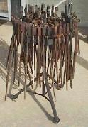
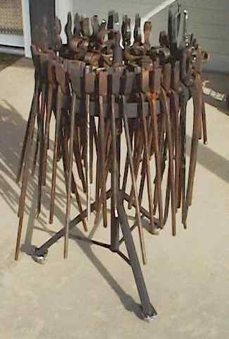
Iron
Wheel Carousel Tongs
Rack
I
was in bad need of a rack
to store my tongs on. They have been living in a five gallon bucket far
too
long, and it has become quite a chore to pick out the pair I need for a
given
job when the pair I need is mixed in with 60-70 other pairs. What I
needed
was a rack that I could organize them on for ease of selection based on
jaw
size. Nahum Hersom had given me some 500 pages
of information
to run copies of, and while looking through that info I found the
perfect
tongs rack for my needs. It was a rotating carousel design built out of
an
old iron wheel. As soon as I had a free Saturday I went down to my
local
junk shop and searched for an old wheel. I found the ideal wheel buried
in
a big pile of other wheels of all sizes and descriptions. My wheel is
20"
in diameter, has a 3/8" x 2" wrought iron forge-welded rim, and eight
1/2"
iron spokes. Even better was the fact that it had an integral 5/8" iron
axle
protruding 2" out each side of its iron hub. I am guessing that the
wheel
was for an old wheel barrow. The wheel exactly matched the mental image
I
had of the ideal wheel for my needs. I was also very happy with the
condition
of the wheel. It was rusted, but it was in excellent overall condition,
showing
no wear or no rust pitting. It would clean up very nicely for painting.
Sometimes
a guy just lucks out. :-)
I
happily paid the $18 that
was marked on it and headed home to build the rack. I decided to build
the
rack support structure with three legs instead of four for two reasons.
Three
legs always sit solidly on the floor, no rocking, and also because it
was
easier to do. On the following Monday I went to our local "House of
Wheels"
to find a good set of casters for the rack. I lucked into some
extremely
fine ball bearing machined steel wheel casters that
must have
been made in China due to the extremely low price. Casters of that
quality
should be $15 each, but they were priced at $3.50! I bought a set and
headed
home to build my tongs rack.
I
used 1-1/4" iron pipe for
the upright post. To fit the 5/8" axle on the wheel, I did a step down
fabrication by inserting two sizes of smaller pipes, one into the
other,
each one 4" long with 2" of exposure in a telescoping fashion, and
brazing
them into permanent place. The final 5/8" pipe was a perfect fit for
the
5/8" axle. The finished rack
is a simple but
effective structure that easily handles the 200+ pounds of tongs. I
organized them on the wheel
rim from the smallest
jaw opening to the largest, and then added the pick-up and special
purpose
tongs. In the center, on the eight spokes, I added a variety
of other
tongs, and my supply of some 20 unfinished horse-hoof nipper tongs.
When
I get time I will convert them to tongs for use with the power hammer,
or
other needs where a rock solid grip is necessary. I particularly enjoy
using
the tongs I made from some of those nippers.
The
finished rack moves easily
where needed on its steel wheel casters, and the carousel rotation of
the
wheel makes selection of the tongs wonderfully convenient. Even loaded
with
all those tongs the wheel rotates very easily with nothing more than a
slight
push with a finger. It is well greased. I particularly enjoy the
historic
nature of the tongs rack, and its convenience and neat appearance adds
a
lot to my shop. The other end of the 5/8" diameter axle sticks up in
the
center of the wheel. I plan to forge a decorative snake that will be
wrapped
around it. The two ends of the snake will be used for hanging tong
locking
rings on so they are convenient to locate and select. I was going to
make
a little tray, but decided the snake would add a nice decorative touch,
and
would do the job just as well. If you are in need of a way to organize
your
tongs, I recommend the iron wheel carousel tongs rack. The iron wheels
are
easily available in most locations, although you may have to search a
little
to find one in the condition of this one. :-)
Double
Reversed Twisting
Jig
The
adjustable length
twisting jig is a very useful
tool for making double
reversed twists in various sized bars. It will allow you to make
virtually
perfect twists every time, if you have the bar
evenly heated when
its placed into the wrench jaws. I like to use an old "Ford wrench" to
make
my double handled twisting wrenches out of. Using a double handled
wrench
will allow you to apply an even force to the bar and not cause it to be
bent
out of alignment during the twisting process. Be sure you use the right
kind
of welding rod when welding the high carbon steel wrench heads to the
jig,
or the welds will break off the first time you use the jig. I use
"UTP-65"
for all such welds, expensive, but worth every penny. Also, because
your
hands rotate under the hot iron during twisting, the hot scale that
falls
off will land on your hand and wrist. Beginners usually find this
uncomfortable,
but you will soon get used to it, and it causes no damage.
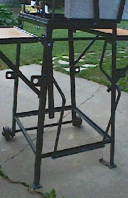
Torch Cart
This image is of a mobile torch cart I
built for my All-States oxy/propane torch. The torch has a pilot flame,
and when using it I like to have a safe and convenient place for the
torch when I need to put it down. I observed this torch cart design at
the NWBA Spring Conference in Sisters, Oregon, at Ponderosa Forge.
I thought it was such an exceptional design that I had to
make one for my shop. I also made a tool tray/table that goes in place
of the torch cradle when I am not using it. That way I can use this
nifty little cart all the time, instead of just for the torch.
The base triangle
is made of 1-1/2" x 1/4" equal leg angle iron, and each side is 2'
long. The upright post is telescoping to allow height adjustment as
desired. The mesh in the triangle is perforated
1/8" aluminum sheet. I made the cradle a little more fancy than the one
I saw in Sisters. I forged some "fingers" on the upper end that wrap
around the end of the torch to prevent it from being accidentlly
knocked off the cradle when I walk by it. The one in Sisters had just a
straight piece of 2" equal leg angle, with a notch cut out for the gas
adjustment valve. The casters are old ones off an old chair, so have a
rod mounting instead of a bolt flange. This is actually a more
desirable type of caster for this application because they can be
mounted at the extreme ends of the triangle corners, providing a larger
"foot-print," and making it more stable. This is a really first class
little torch cart, and I want to thank Jeff , of Ponderosa Forge, for
making this outstanding design available to all those attending the
conference.
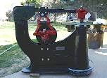
Universal
Postition Welding Jig Table
I built a table
to allow me to easily weld the many welds on the little trivet table
above (it is 6" square). I had to make many of them, and wanted to be
able to position all the welds for flat position welding to insure the
highest quality welds I can produce. The table top can spin 360
degrees, either by the ball joint
itself, or by the 360 degree swivel joint just below it...the
bright shiny vertical rod section in the image. The table can also tilt
to 20 degrees past vertical, or 110 degrees from horizontal. The swivel
socket is a very slightly tapered interference fit socket that will
rotate when lifted slightly, but locks into position when weighted to
prevent the table from moving while being used. The ball joint is made
from an old 2" diameter, long stemmed, tow hitch ball, and the ball
clamp was forged from 3/8" x 1-1/2" bar stock. I
elected to use the old tow ball for two reasons, one being that it has
such a long stem on it which allows the table to tilt to 20 degrees
past vertical, and the other being that it is not chromed and will
provide more friction to keep the table in the position it is set to
without having to adjust the clamp tension.
You will notice that that
table can swivel from either the ball joint, or the swivel joint below
it. I did that because the ball joint will not allow the tilting of the
table to vertical in all directions due to the way the clamp jaws hold
the ball. I wanted to be able to tilt the table past vertical in all
directions, so added the swivel joint to allow one of the two slots in
the ball joint clamp to be positioned in any direction to allow this.
Also, to gain the extreme amount of tilt for the table I had to attach
the ball to the table top, and not to the upright of the table support.
This arrangement allows me to tilt the table to vertical, and then spin
the table, via the ball joint, to access each corner weld on the frame
in turn. It is a wonderful feature.
In use the table
is a dream come true. The ball joint tension is left untouched most of
the time, and the table is changed in its position by simply grabbing
the edges and tilting to the new desired position.I have my jigs set up
to work together for the various stages of construction, first the
square frame fabrication, then the welding on of the four legs. I have
the first stage jig tack welded to the 3/16" thick steel plate table
top. The leg jig is added, with four wing nutted bolts, when I am ready
to start that operation. I do everything in batches of 20-25 units. One
other very nice feature is that I clamp the ground cable to the base of
the table support column and just forget about it. The tension in the
ball joint, and in the interference fit swivel joint, allows the
current to pass right through them without any arcing problems.
You may want to use conductive grease, but I have not found
it necessary so far.
If you have a lot
of welding to do, this table may be the answer to your needs. Give it a
try and let me know how it goes. It can be used for anything that can
be clamped to the table top surface, jigs are not necessary.
:-)
Some Blacksmithing and Foundry Links
My
Forge and Burner Design Page
ABANA
Visit
the Late Chris Ray's Home Page
Metal
Web News
John
Bump's Foundry Page...great stuff for beginners!
Cameron
McKeown's Foundry Page...great stuff this one!
Rick
Berry's Foundry Page....Good Stuff!
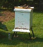
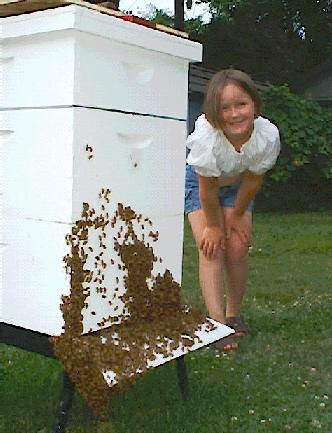
My Bees
Hive on forged iron stand.
I
was thrilled
when I looked up from my forging work to see a big swarm of honeybees
filling
the air in my yard. They settled on a branch in my hedge and I quickly
decided
that they were going to come live with me. I got my 6 year old daughter
Natalie
to join me to watch them settle on the branch, and then I let her stand
back
while I captured the swarm in a cardboard box. Natalie quickly became
at
ease with them and allowed them to walk on her arms and bare skin
without
any fear or stings. She was quite impressed
seeing her Daddy's
bare arms and face covered with bees but not being stung, and that
convinced
her that it was OK to let them land on her too. She
did get a
sting a few days later when she sat on one, but it has not dampened her
trust
or appreciation of them at all. She knows it was her fault for sitting
on
the bee, not the bee's.
Two days later another
very big swarm arrived at my school and I was just barely able to save
them
from the exterminator who had been called to kill them. I put them into
another
cardboard box and placed that box next to the the first one in my back
yard.
Both swarms lived in their boxes for about 2 weeks while I gathered the
beekeeping equipment and built the hive bodies for them to be moved
into.
Finally all was assembled, painted, and an iron stand forged for the
hive
to sit on.
Combining the two swarms
into one hive was not difficult, but was extremely messy. They had
managed
to make quite a number of combs and partially fill them with brood,
pollen,
and honey, in the short time they had been in the boxes. I had honey
all
over the place as I removed the combs and transferred the bees into the
new
hive body. The two swarms were different varieties of bees, one was
Italian,
and the other appeared to be German. The queens fought and it appears
that
the Italian queen was the victor, based on the emerging young bees I am
seeing.
That is a good outcome as I would much prefer the Italians due to their
gentle
disposition and all around good qualities. I will requeen the
hive
next Spring with an Italian queen however, since I have no way of
knowing
how old this queen is. Now I just want to see them put enough stores up
to
last them through the coming winter. Any honey I get this year will be
just
frosting on the cake, or honey on the pancakes, although I do not
expect
any. :-)
My
bees have become
an integral part of my every day life. Every day in the
Summer after
working at the forge, I shut down for the day and spend several hours
relaxing
in front of my hive while I watch what is going on. Several times a
week
I have to shut my forge down early when I see bees covering the front
of
the hive due to a heavy honey flow. I want to experience what they are
experiencing, so I move my chair up to within a couple feet of the hive
and,
with my beer in hand, kick back and enjoy the spectacle. I am often
covered
with resting bees, and for a short time become part of the intense
activity
that they are going through. The music of their wings is probably the
best
part of the experience, and the sound can become very intense when
thousands
of my little girls are flying around me trying to get a position in the
landing
pattern. I know that anyone who is part of the natural world around
them
will understand my words, and for those who do not understand my
viewpoint,
there is still time for you to become part of the world that gave rise
to
you. Don't pass up the chance and opportunity. You will never regret
it.
It, and family, are the only things that have real meaning in this
world,
and the natural world will be here long after we are only fossils in
the
rock!

Click the image for a full sized picture, or
here for a closer of the
bees, or
here for a very close view.
These images were taken
on 3 July 01 at the end of a 102 degree day. The bees are too hot in
the
hive even though I provided them shade all day. An hour later, after
dark,
the number of bees "taking the air" had almost doubled. They were all
back
in the hive by the following morning.
Update
2000: I have now cared for my bees for
a full Summer, and
brought them through the Fall. The work involved in medicating them was
quite
an eye opener, and was much greater than necessary 40 years ago. I was
a
"beehaver" back in the 60's, but I am now a "beekeeper", and there is a
great
difference. The first thing I did was to get rid of my gloves. I now
use
bare arms and hands to work with my bees, and for most of the Summer I
did
not wear any beekeeping gear at all, just shorts and T-shirt, when I
opened
my hive up to work with them. I had only three stings during the entire
Summer
and Fall, and all three were totally my fault. As an example, I was all
done
working with the bees, and after putting the hive back together, I was
walking
back to the shed when I suddenly had an extremely hot spot develop in
my
armpit. I had put my arm down on a bee that had landed on my T-shirt
right
in my armpit. Now I don't know about you, but if someone stuck my nose
into
"my" armpit at the end of a hot day in August, I would probably sting
too!
I did not get one single sting that I don't feel was totally justified
on
the part of the bee. Honeybees do not fly around looking for someone to
sting.
Working bees this way,
as part of their world, and understanding them, has changed my entire
way
of looking at them, and life. I used to consider my bees somewhat of a
threat,
and would cover myself up as much as possible when I needed to work
with
them. I once received over 50 stings when I opened my hives up one cold
damp
morning in Oregon in 1966, but that was 100% my fault. It is a
wonderful
thing to become one with them, and understand them to a degree that I
can
now feel confident in opening them up with virtually no protection at
all.
Three times I have had guests, my brother being one of them, who wanted
to
look into my hive. I convinced them that they would be safe dressed as
they
were, and I opened the hive up. We pulled out frames covered with
thousands
of bees, but not a single sting did anyone receive, even though
thousands
of bees were flying all around us. I am finally beginning to feel that
I
have actually become a beekeeper, and there is more satisfaction in
that
knowledge than I can possibly convey in this narrative. It is an
experience
much deeper than can be encountered in our superficial daily lives
where
we watch TV to vicariously experience nature. In my life I have
"visited"
with a pod of whales, ridden the backs of 14 foot Tiger sharks in the
Caribbean,
and walked in the presence of the great brown bears of Alaska, but my
bees
are the most memorable and important to me. Our future depends on them,
and
on all the other creatures that make up the complex web of life. Shall
we
forever break the web whenever we touch it? If we are to survive into
the
future we must learn how to live as part of nature, and not outside of
nature.
We are part of the web, not apart from it and looking down upon it.
Update
2001: Well, another season has passed
into history, and my
bees are still making their living, no thanks to me, although I did get
all
their medications taken care of. This past summer was one of intense
labor
for me, as I worked as much as 18 hours a day, seven days a week, to
get
my new shop to a point
where it would be snug, warm,
and operational, by the time Fall arrived. I
requeened the hive
in May, and missed my opportunity to put a special super on the hive to
produce
individual little round comb honey packets. I was too involved with the
shop
to pay attention to the needs of the hive, and consequently lost a big
swarm
in early summer. The hive was incredabley active one day, and the next
there
were only a few listless bees siting around the entrance wondering what
had
happened. That depressed me greatly, but I didn't have the time to morn
the
loss. Fortunately the remaining queen did her job well, and soon the
hive
was buzzing with activity again. I ended the season harvesting one
super
of honey, and two hive bodies packed with bees, so I am in good shape
going
into winter. I look forward to managing my bees much more carefully
next
season. :-)
Update
2002:
This was a very successful year for my beekeeping activities. I wanted
to
see if I could be successful producing honey in little rounds, the most
intensive
and difficult kind of hive management. This image
shows the harvest. I only had one "Ross Rounds Super" on the hive this
year
to see if I could get them to fill the rounds. All 32 rounds were
completely
and perfectly filled on both sides. I was extremely pleased, to put it
mildly.
I will expand to two Ross Supers next year, and if they can fill both
completely,
I may even try three the following year. The honey is excellent. Its
wonderful
to have such a nice, even if small, harvest this year.
:-)
Not
having experience
in using Ross supers, I made one mistake. I knew I needed to keep the
bees
crowded to force them into the Ross Super, but
I over-did it a
little, and the result was a total filling of every nook and cranny in
the
hive with honeycomb. Even the space between the hive bodies, and the
space
between the top super and the inner cover, was totally packed with
honey
filled comb. That is where all the extracted honey came from. I will be
a
little more careful next year in order to prevent a repeat of this
happening
again. All that spur comb created a huge sticky mess when I opened up
the
hive to take the honey off. My wife Gretchen was very happy to have the
extracted
honey however, so no honey went to waste except what dripped on the
grass,
and the bees reclaimed most of that.
Me in my
Utilikilt
-
superior wear for
blacksmithing -or- how to get toasty
knees. :-)
Me, the Z, and
the Kilt
My
Younger Daughter and Me at the Hagerman National
Fish Hatchery
Thank You For the Visit
I no longer offer
support for forge or design problems, but if you wish to contact me for
other reasons you may use the e-mail link at the bottom of this page.
Thank you. Ron Reil

(Return to my home page)
Page By: Ron Reil
©Golden Age Forge
23 Nov 07

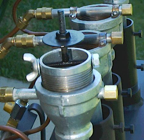
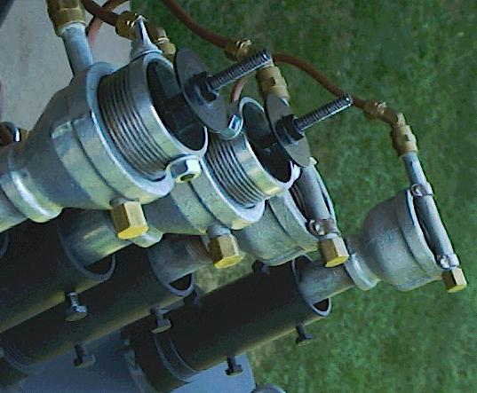
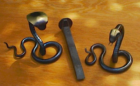
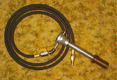
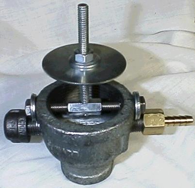
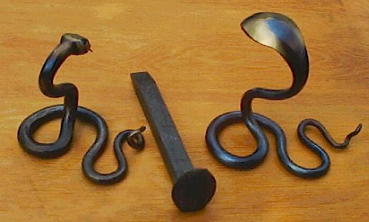
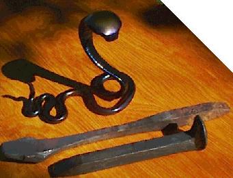
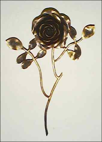
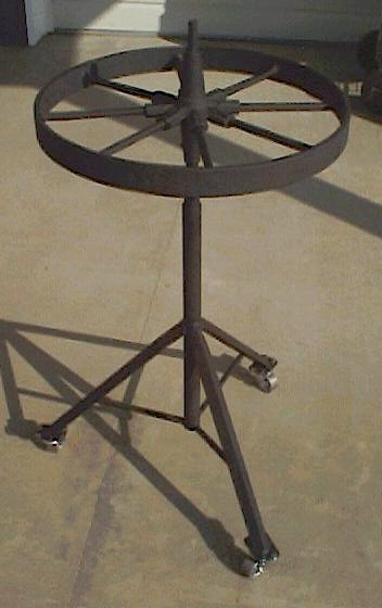
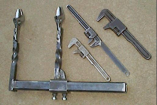
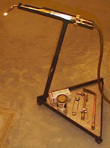
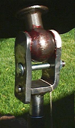
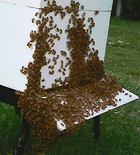
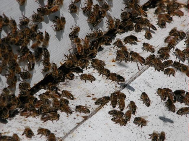
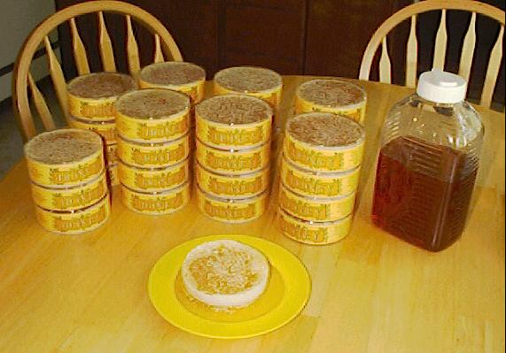
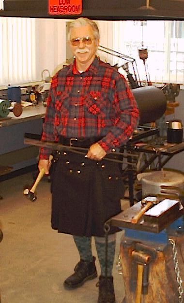
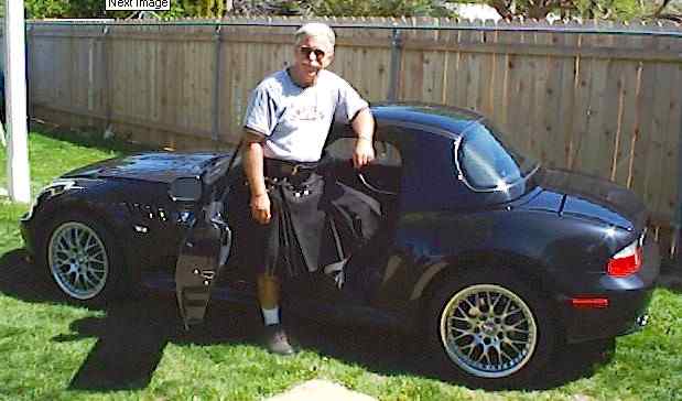