
The Construction of My Freon Tank Miniforge
Read an e-mail I received about this forge on 12/23/00
Contact me by phone: (208)
462-4028
Note: Due to spam problems I no longer post my e-mail address.
The Full Site Map - Lists All Pages on
This Site
The Shepherd's Hook Forge it's Not ...
But it Could Be
![]() I provide the
following information as a service
to the blacksmithing community. Although the designs I employ in
building
my burners and forges are safe and reliable in the way that I use them,
the
same may not be the case for you. You assume all risk in
using this
information, or any other information on this page. Other
designs that
I have posted here have been submitted by other smiths, and I have no
experience
with most of them. Use care and good sense in using any of these
designs.
Get help from a knowledgeable smith if you are new to this work. Don't
take
chances because these tools can cause injury, blindness, or even death,
if
used improperly. Also, be sure you are in a well ventilated space
(see the Nighthawk CO
& explosive gas
detector paragraph), or better yet, work outside.
Additionally, never
operate a forge that is connected directly to a propane tank that is
near
a forge, or indoors. An emergency pressure valve release
could instantly
place you in the middle of a fireball. Follow all local codes regarding
indoor use of propane, and I believe indoor use of a propane
tank violates
code everywhere in North America, and most of Europe. A new concern has
arisen
with the introduction of the "Mongo Burner Series." Please read
carefully
all the information in the separate "Safety
Warnings and Considerations" information which heads the
"Mongo Burner
Series" section. Thank you.
I provide the
following information as a service
to the blacksmithing community. Although the designs I employ in
building
my burners and forges are safe and reliable in the way that I use them,
the
same may not be the case for you. You assume all risk in
using this
information, or any other information on this page. Other
designs that
I have posted here have been submitted by other smiths, and I have no
experience
with most of them. Use care and good sense in using any of these
designs.
Get help from a knowledgeable smith if you are new to this work. Don't
take
chances because these tools can cause injury, blindness, or even death,
if
used improperly. Also, be sure you are in a well ventilated space
(see the Nighthawk CO
& explosive gas
detector paragraph), or better yet, work outside.
Additionally, never
operate a forge that is connected directly to a propane tank that is
near
a forge, or indoors. An emergency pressure valve release
could instantly
place you in the middle of a fireball. Follow all local codes regarding
indoor use of propane, and I believe indoor use of a propane
tank violates
code everywhere in North America, and most of Europe. A new concern has
arisen
with the introduction of the "Mongo Burner Series." Please read
carefully
all the information in the separate "Safety
Warnings and Considerations" information which heads the
"Mongo Burner
Series" section. Thank you.
![]() An
additional item that should be of interest to you is
obtaining an
explosive gas/CO detector for your working space.
Mark Manley, of
"Manley Metal Works,"
Silverton, Oregon, provided a short piece of very important information
in
the Winter 2000 issue of "Hot Iron News" that I feel needs to be passed
on
to a wider audience. There is a very reasonably priced digital read-out
combination explosive gas and CO detector available in local hardware,
building
supply, and other stores. I was concerned about having a CO monitor in
my
shop, even though I have a very good induced draft hood in my shop. The
detector
is made by "Kidde Safety" and is called the "Nighthawk."
I
will not go into the specs for the instrument here, it is available on
the
Internet if you look up "Kidde Safety," but will say that it is a very
finely
designed and built instrument. It runs on 110VAC, and has a 12VDC
back-up.
It plugs directly into an outlet, or the transformer plug detaches for
remote
mounting, up to 6' from the plug. You can easily check your CO level
with
a quick glance at the digital read-out, and if it detects either
propane
or natural gas will instantly sound an audible alarm, and the word
"Gas"
will display on the digital display. If it detects a 50 PPM threshold
level
of CO, it will also sound a different audible alarm. Also, you will
know
its operating because the blinking decimal point in the digital
read-out
indicates its operating and sampling the air in your shop.
An
additional item that should be of interest to you is
obtaining an
explosive gas/CO detector for your working space.
Mark Manley, of
"Manley Metal Works,"
Silverton, Oregon, provided a short piece of very important information
in
the Winter 2000 issue of "Hot Iron News" that I feel needs to be passed
on
to a wider audience. There is a very reasonably priced digital read-out
combination explosive gas and CO detector available in local hardware,
building
supply, and other stores. I was concerned about having a CO monitor in
my
shop, even though I have a very good induced draft hood in my shop. The
detector
is made by "Kidde Safety" and is called the "Nighthawk."
I
will not go into the specs for the instrument here, it is available on
the
Internet if you look up "Kidde Safety," but will say that it is a very
finely
designed and built instrument. It runs on 110VAC, and has a 12VDC
back-up.
It plugs directly into an outlet, or the transformer plug detaches for
remote
mounting, up to 6' from the plug. You can easily check your CO level
with
a quick glance at the digital read-out, and if it detects either
propane
or natural gas will instantly sound an audible alarm, and the word
"Gas"
will display on the digital display. If it detects a 50 PPM threshold
level
of CO, it will also sound a different audible alarm. Also, you will
know
its operating because the blinking decimal point in the digital
read-out
indicates its operating and sampling the air in your shop.
![]() I bought one of
these
instruments for my shop, and was so impressed with it that I went down
and
bought a second one for my home, which has natural gas heat, gas hot
water,
and a natural gas fireplace insert. I priced CO detectors on the
McMaster-Carr
web site, and they alone were $170, where this combination instrument
is
only $59 at my local Home Depot. Considering how deadly CO can be, this
instrument is very inexpensive, well worth the investment, and it may
well
save your life. After Mark installed his "Nighthawk," he discovered
that
he had been exposing himself to CO levels from 30-160 PPM for a long
time
while running his forge! Thanks for the tip Mark.
I bought one of
these
instruments for my shop, and was so impressed with it that I went down
and
bought a second one for my home, which has natural gas heat, gas hot
water,
and a natural gas fireplace insert. I priced CO detectors on the
McMaster-Carr
web site, and they alone were $170, where this combination instrument
is
only $59 at my local Home Depot. Considering how deadly CO can be, this
instrument is very inexpensive, well worth the investment, and it may
well
save your life. After Mark installed his "Nighthawk," he discovered
that
he had been exposing himself to CO levels from 30-160 PPM for a long
time
while running his forge! Thanks for the tip Mark.
Note: There has been a recall of Kidde Safety "Nighthawk" gas and CO detectors. This does not affect any detectors sold after the date that I posted the above information, however you may check your unit by going to http://www.cpsc.gov/cpscpub/prerel/prhtml99/99082.html.
A Word About Obtaining My Help
![]() I am no longer
able
to offer my support to help solve problems you may have with your
burners
or forge. I have reached the point that something has to give. Two to
three
hours a night answering questions has brought my metal working each
evening
of the week to a stand still. I will continue to update my
blacksmithing
pages, and will now also have the time to clean out all the outdated
and
conflicting information in my pages, however, I will no longer be able
to
troubleshoot your system. I still want to receive your e-mails if they
do
not pertain to forge or burner problems. If you build your burner to
the
design specs and information shown and discussed on my pages, including
in
the Troubleshooting Document and FAQ, your burner should work well. If
it
doesn't, then its not built correctly, and you will need to make some
adjustments
after looking through the available information. The best thing to look
at
when fine tuning your burner are the various flame
images I have posted.
If yours looks like these images, you have it right. Here are a few
helpful
links.
I am no longer
able
to offer my support to help solve problems you may have with your
burners
or forge. I have reached the point that something has to give. Two to
three
hours a night answering questions has brought my metal working each
evening
of the week to a stand still. I will continue to update my
blacksmithing
pages, and will now also have the time to clean out all the outdated
and
conflicting information in my pages, however, I will no longer be able
to
troubleshoot your system. I still want to receive your e-mails if they
do
not pertain to forge or burner problems. If you build your burner to
the
design specs and information shown and discussed on my pages, including
in
the Troubleshooting Document and FAQ, your burner should work well. If
it
doesn't, then its not built correctly, and you will need to make some
adjustments
after looking through the available information. The best thing to look
at
when fine tuning your burner are the various flame
images I have posted.
If yours looks like these images, you have it right. Here are a few
helpful
links.
Note: If you e-mail me, please be sure your e-mail in "txt" (text) format, not html. I am now averaging two to three virused e-mails each time I download my e-mail, so I have to be very careful. If your e-mail is not in "txt" format I will most likely delete your e-mail without opening it in order to protect from possible virus infection. It's certainly sad that we have idiots in our society that feel they must cause such problems.
Forge & Burner Troubleshooting Document
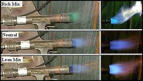
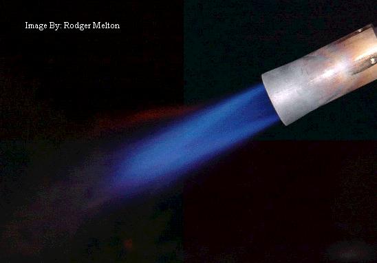
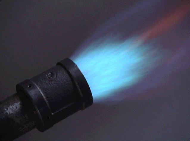
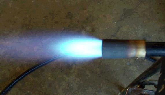
1) T-Rex Flame Image - Ideal Neutral Flame
2) Side-arm Burner Flame Using Temporary Cast Iron Test Nozzle - Slightly Reducing Flame
3) Another Flame Image - Oxidizing Flame
![]() The bottom three
flame
images give you views of burner flames adjusted to 1) neutral, 2)
slightly
reducing, and 3) strongly oxidizing. The burners have nothing to do
with
it, just the choke settings. All of these images could have been done
with
the T-Rex, or Side-arm burners. At your high end gas pressure, if you
have
achieved a flame similar to the oxidizing flame shown in the bottom
image,
#3, you will then have full control over the burner flame across the
full
pressure range. This will allow you to achieve oxidizing, neutral, or
reducing,
flames as needed by simply adjusting the choke. You will then have a
properly
functioning burner.
The bottom three
flame
images give you views of burner flames adjusted to 1) neutral, 2)
slightly
reducing, and 3) strongly oxidizing. The burners have nothing to do
with
it, just the choke settings. All of these images could have been done
with
the T-Rex, or Side-arm burners. At your high end gas pressure, if you
have
achieved a flame similar to the oxidizing flame shown in the bottom
image,
#3, you will then have full control over the burner flame across the
full
pressure range. This will allow you to achieve oxidizing, neutral, or
reducing,
flames as needed by simply adjusting the choke. You will then have a
properly
functioning burner.
About This Page
![]() This page
is
a rough step by step record of the construction of my Freon tank
"Mini-Forge,"
the smallest of my four forges. There are many forges
out there that
have been constructed from Freon tanks, but this one is a little bit
different
from most of them. I will provide a simple
description, along with
images, but this is not designed to be a step by step set of
construction
plans. Also, I get most of my
refractory supplies locally
from an excellent pottery supply shop. I have no
additional resources
other than those listed on my main Forge
and Burner
Design Page, in the subsection titled
"Sources
For Refractory
Materials,"
so please don't ask for anything
additional, as I just don't have anything for you. You will have to
explore
for materials sources on your own if my listed sources don't have what
you
want. Thank you.
This page
is
a rough step by step record of the construction of my Freon tank
"Mini-Forge,"
the smallest of my four forges. There are many forges
out there that
have been constructed from Freon tanks, but this one is a little bit
different
from most of them. I will provide a simple
description, along with
images, but this is not designed to be a step by step set of
construction
plans. Also, I get most of my
refractory supplies locally
from an excellent pottery supply shop. I have no
additional resources
other than those listed on my main Forge
and Burner
Design Page, in the subsection titled
"Sources
For Refractory
Materials,"
so please don't ask for anything
additional, as I just don't have anything for you. You will have to
explore
for materials sources on your own if my listed sources don't have what
you
want. Thank you.
![]() Note:
I have intentionally produced this page using a small font
size to make
printing of the page for use as an instruction sheet more convenient.
If
you find it difficult to read this small font, your bowser has font
size
selections which can enlarge it for you.
Note:
I have intentionally produced this page using a small font
size to make
printing of the page for use as an instruction sheet more convenient.
If
you find it difficult to read this small font, your bowser has font
size
selections which can enlarge it for you.
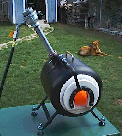
The Freon Tank Mini-forge
![]() Dimensions: The finished dimensions of the Freon
Tank Mini-forge,
as measured from cut end to cut end of Freon tank are 11-1/2",
and 9-1/2"
in width. The interior chamber dimensions can only be roughly given
because
of its horseshoe shape, flat floor, and rough Kaowool interior surface.
It
is roughly 4" in diameter and 9-1/4" long. This calculates out to
approximately
116 cubic inches of chamber volume, or 0.4 of the total 300 cubic inch
volume
a "Reil or EZ Burner"
can heat to forge
welding temperature if the chamber is ITC-100 coated. If a
Nanomongo burner were
to be used in this forge
it would be a searingly
hot forge indeed,
for sure requiring UV eye and skin protection against UV flash burn.
Dimensions: The finished dimensions of the Freon
Tank Mini-forge,
as measured from cut end to cut end of Freon tank are 11-1/2",
and 9-1/2"
in width. The interior chamber dimensions can only be roughly given
because
of its horseshoe shape, flat floor, and rough Kaowool interior surface.
It
is roughly 4" in diameter and 9-1/4" long. This calculates out to
approximately
116 cubic inches of chamber volume, or 0.4 of the total 300 cubic inch
volume
a "Reil or EZ Burner"
can heat to forge
welding temperature if the chamber is ITC-100 coated. If a
Nanomongo burner were
to be used in this forge
it would be a searingly
hot forge indeed,
for sure requiring UV eye and skin protection against UV flash burn.
![]() Burner
Mounting: The Nanomongo burner, or T-Rex, produce such
intense vacuum
and gas stream pressure that they can be mounted horizontally along the
base
mounting structure of the forge, and a supply pipe run up to a short
nozzle
mounted in the forge shell. This would make the forge much
neater in
appearance, without the long burner tube sticking up and out to the
side.
The burner would act like a carburetor to supply the gas mix to the
supply
line or manifold. Because the gas in the supply line is an air and
propane
mixture, flashback will occur while shutting down the system when
the gas stream velocity drops below the burn velocity. This should not
be
a problem other than creating a "pop" when the gas supply valve is
closed.
The greater the volume of the supply plumbing, the greater will be the
flash
back effect. If you opt to use this method, be sure to use supply line
and
manifold line diameters of sufficient size to prevent excessive
back-pressure
on the supply burner.
Burner
Mounting: The Nanomongo burner, or T-Rex, produce such
intense vacuum
and gas stream pressure that they can be mounted horizontally along the
base
mounting structure of the forge, and a supply pipe run up to a short
nozzle
mounted in the forge shell. This would make the forge much
neater in
appearance, without the long burner tube sticking up and out to the
side.
The burner would act like a carburetor to supply the gas mix to the
supply
line or manifold. Because the gas in the supply line is an air and
propane
mixture, flashback will occur while shutting down the system when
the gas stream velocity drops below the burn velocity. This should not
be
a problem other than creating a "pop" when the gas supply valve is
closed.
The greater the volume of the supply plumbing, the greater will be the
flash
back effect. If you opt to use this method, be sure to use supply line
and
manifold line diameters of sufficient size to prevent excessive
back-pressure
on the supply burner.
![]() This little
forge is the smallest of my four forges, two coal, and two propane. I
sold
my commercial natural gas forge a few years ago, or it would
be my 5th
forge. It is not designed to be my everyday forge, but to be an easily
portable
forge that I can use for demos, remote heating requirements, or just
when
I need to take a quick heat on a small piece of
iron. I would not
suggest you build one this small for a first or primary forge. It is
too
limited in what it can hold for regular forging, although it would be a
very
fine bladesmithing forge if you didn't wish to make long blades, say
10"
or less. It could handle a longer blade if needed by having the end
stick
out the back of the forge. It would serve very well
for making small
hand tools, like chisels and gouges, if you are a woodworker. In fact
it
would be superb for such use.
This little
forge is the smallest of my four forges, two coal, and two propane. I
sold
my commercial natural gas forge a few years ago, or it would
be my 5th
forge. It is not designed to be my everyday forge, but to be an easily
portable
forge that I can use for demos, remote heating requirements, or just
when
I need to take a quick heat on a small piece of
iron. I would not
suggest you build one this small for a first or primary forge. It is
too
limited in what it can hold for regular forging, although it would be a
very
fine bladesmithing forge if you didn't wish to make long blades, say
10"
or less. It could handle a longer blade if needed by having the end
stick
out the back of the forge. It would serve very well
for making small
hand tools, like chisels and gouges, if you are a woodworker. In fact
it
would be superb for such use.
An Update: I recently had to do some upsetting on the ends of two 1" square pieces of 1085 steel bar. They were to be used for the posts on two ball topped stake tools, one of 4", and the other 5" diameter. The weather was questionable, so I elected to use this little forge instead of my big one. It took about 4 hours to complete each post by the time I had formed the cup and perfected the shape of each one to my satisfaction. The diameter of the upset portion when finished was almost 2". The little forge did an outstanding job of heating the heavy steel, even though the opening was quite small for easy handling of the metal. This forge can handle much larger sections than I would have thought.
Some Background Information
![]() You can
often
obtain empty Freon tanks from your local recycling yard. There are
about
50 of them sitting in mine at the time of this writing. If that doesn't
produce
results, check with some of your local heating and AC shops. They have
them
and generally burn holes in the top or side before disposing of them.
If
you explain what you want it for they may be happy to give you one.
They
tend to be wary of guys who want them for air receiver tanks, since
that
is an illegal use and can get them in trouble, the reason they burn
holes
in them prior to disposal.
You can
often
obtain empty Freon tanks from your local recycling yard. There are
about
50 of them sitting in mine at the time of this writing. If that doesn't
produce
results, check with some of your local heating and AC shops. They have
them
and generally burn holes in the top or side before disposing of them.
If
you explain what you want it for they may be happy to give you one.
They
tend to be wary of guys who want them for air receiver tanks, since
that
is an illegal use and can get them in trouble, the reason they burn
holes
in them prior to disposal.
![]() Scribe
circles
on the ends to allow you to cut the ends out, grind to final shape, and
end
up with a good circular hole on both ends that is well centered. You
will
be limited in how small you can cut the top end out because of the
blow-off
plug. Cut it out as small as you can however, as the curved in ends
provide
great structural strength, and will also secure the Kaowool in the
forge
in a superior manner. And besides, it just looks good.
Scribe
circles
on the ends to allow you to cut the ends out, grind to final shape, and
end
up with a good circular hole on both ends that is well centered. You
will
be limited in how small you can cut the top end out because of the
blow-off
plug. Cut it out as small as you can however, as the curved in ends
provide
great structural strength, and will also secure the Kaowool in the
forge
in a superior manner. And besides, it just looks good.
![]() I used my
portable
"EZ- Burner" for this forge, and decided for portability and easy
storage
I didn't wish to tie up a burner permanently as part of the forge. This
idea
has proved to be an excellent one, requiring only insertion of the
burner
nozzle up to the nozzle collar, and gently tightening three thumb
screws...takes
all of 10 seconds to do. Also, when I am finished with the forge I can
quickly
loosen the screws and pull the burner out so that it doesn't act like a
chimney,
venting the extremely hot chamber gasses through the burner and heating
it
excessively. The burner is cool to the touch at the moment of shut
down,
but will quickly get very hot from the exhaust gasses.
I used my
portable
"EZ- Burner" for this forge, and decided for portability and easy
storage
I didn't wish to tie up a burner permanently as part of the forge. This
idea
has proved to be an excellent one, requiring only insertion of the
burner
nozzle up to the nozzle collar, and gently tightening three thumb
screws...takes
all of 10 seconds to do. Also, when I am finished with the forge I can
quickly
loosen the screws and pull the burner out so that it doesn't act like a
chimney,
venting the extremely hot chamber gasses through the burner and heating
it
excessively. The burner is cool to the touch at the moment of shut
down,
but will quickly get very hot from the exhaust gasses.
![]() The
materials
used in constructing the forge are; two layers of 1" thick Kaowool
chamber
insulation, 1" thick Kaowool board for the end panels, and a 4" wide
piece
of a high alumina 1" thick kiln shelf for the floor. Note: The 1"
Kaowool
will expand while handling it to around 2", so will seem like its far
more
than 1" thick. The floor slab sits on compressed Kaowool, as well as
four
1" kiln shelf posts that sit on the bolt protrusions that hold the
forge
support leg structure on. I fabricated the burner
mounting from a
large "B" grade construction washer for the flange, and a piece of pipe
brazed
into the center hole of the washer for the mounting tube to hold the
burner.
The pipe is a very close fit to the outer diameter of the
burner nozzle.
I drilled and tapped three 1/4"- 20 thumb screw holes in the tube as
shown
in the images. Be sure you form the washer to match the forge shell
radius
before you braze in the pipe section. The washer will require annealing
before
you can cold work it, or you can just work it hot if you prefer. I
worked
it cold to prevent scaling. It needs to closely fit the radius of the
outer
surface of the forge shell. You will also have to grind off a
little
of the weld rib that circles the tank where the washer will contact the
shell
to allow a close fit. Attach the collar to the forge shell with two or
three
1/4" counter sunk machine bolts. You can get
whatever kind of adjustable
feet and carrying handle you prefer. My handle is solid brass, which
does
get too hot to handle while the forge is in operation. You may prefer a
different
design.
The
materials
used in constructing the forge are; two layers of 1" thick Kaowool
chamber
insulation, 1" thick Kaowool board for the end panels, and a 4" wide
piece
of a high alumina 1" thick kiln shelf for the floor. Note: The 1"
Kaowool
will expand while handling it to around 2", so will seem like its far
more
than 1" thick. The floor slab sits on compressed Kaowool, as well as
four
1" kiln shelf posts that sit on the bolt protrusions that hold the
forge
support leg structure on. I fabricated the burner
mounting from a
large "B" grade construction washer for the flange, and a piece of pipe
brazed
into the center hole of the washer for the mounting tube to hold the
burner.
The pipe is a very close fit to the outer diameter of the
burner nozzle.
I drilled and tapped three 1/4"- 20 thumb screw holes in the tube as
shown
in the images. Be sure you form the washer to match the forge shell
radius
before you braze in the pipe section. The washer will require annealing
before
you can cold work it, or you can just work it hot if you prefer. I
worked
it cold to prevent scaling. It needs to closely fit the radius of the
outer
surface of the forge shell. You will also have to grind off a
little
of the weld rib that circles the tank where the washer will contact the
shell
to allow a close fit. Attach the collar to the forge shell with two or
three
1/4" counter sunk machine bolts. You can get
whatever kind of adjustable
feet and carrying handle you prefer. My handle is solid brass, which
does
get too hot to handle while the forge is in operation. You may prefer a
different
design.
![]() The forge
is
painted with high temperature stove paint, as is the forge support leg
structure.
I cold bent the support structure from shear drops that I had in my
rack.
You may use whatever looks good and is available in your stock rack.
The
last step in the construction process was to coat all interior surfaces
with
ITC-100. Any gas forge will operate at higher temperatures, heat the
steel
quicker, and experience significant fuel savings, with the use of this
Zircon
ceramic IR reflecting refractory coating. It will protect the Kaowool
from
erosion and prevent dangerous ceramic fibers from coming out in the
exhaust
of the forge. It is worth the cost and effort to
coat your forge chamber
with this excellent material.
The forge
is
painted with high temperature stove paint, as is the forge support leg
structure.
I cold bent the support structure from shear drops that I had in my
rack.
You may use whatever looks good and is available in your stock rack.
The
last step in the construction process was to coat all interior surfaces
with
ITC-100. Any gas forge will operate at higher temperatures, heat the
steel
quicker, and experience significant fuel savings, with the use of this
Zircon
ceramic IR reflecting refractory coating. It will protect the Kaowool
from
erosion and prevent dangerous ceramic fibers from coming out in the
exhaust
of the forge. It is worth the cost and effort to
coat your forge chamber
with this excellent material.
What Burner to Use
![]() There are a
wide variety of burners to chose from on my Forge
and Burner Design Page that will do a good job with this
forge. The standard
work-horse burners have been the "Reil and EZ-Burners," but now there
is
a new choice that you should consider. As you can see from the
e-mail I have at the top of the
page, the standard burners
will do everything you may ever need, but the new
"Minimongo Burner"
is an alternative that
has a much higher output, but it is also larger in diameter, 1-1/4"
burner
tube, and is really too much burner for this little forge. A better
choice
might be the Micromongo,
which is a 3/4" bore, just like the "Reil Burner." I should add one
thing.
I have information about the Reil and EZ Burners posted on two
different
pages. One source is located on my Forge
Page, and the other on my Forge
and Burner
Design Page. These links will take you directly to the
specific "Reil/EZ"
burner information. Please read both pages if you want all the
necessary
information. You may also want to have a look at the new Side-Arm
burner
design, which is in the Mongo section on my Design page. It has now
been
perfected, and its an excellent burner.
There are a
wide variety of burners to chose from on my Forge
and Burner Design Page that will do a good job with this
forge. The standard
work-horse burners have been the "Reil and EZ-Burners," but now there
is
a new choice that you should consider. As you can see from the
e-mail I have at the top of the
page, the standard burners
will do everything you may ever need, but the new
"Minimongo Burner"
is an alternative that
has a much higher output, but it is also larger in diameter, 1-1/4"
burner
tube, and is really too much burner for this little forge. A better
choice
might be the Micromongo,
which is a 3/4" bore, just like the "Reil Burner." I should add one
thing.
I have information about the Reil and EZ Burners posted on two
different
pages. One source is located on my Forge
Page, and the other on my Forge
and Burner
Design Page. These links will take you directly to the
specific "Reil/EZ"
burner information. Please read both pages if you want all the
necessary
information. You may also want to have a look at the new Side-Arm
burner
design, which is in the Mongo section on my Design page. It has now
been
perfected, and its an excellent burner.
![]() I need to
update
this section to include the
"Shorty
Burner,"
which was designed specifically for this forge by Mike Porter in
Seattle,
and is being commercially produced by
Rex Price
in Georgia. I have
information about the burner on my Forge Design page, which is linked
in
the previous sentence, but you can go
directly to Rex's web site if you wish. This is the perfect
burner for
this forge, and really turns it into a beautiful tool.
I need to
update
this section to include the
"Shorty
Burner,"
which was designed specifically for this forge by Mike Porter in
Seattle,
and is being commercially produced by
Rex Price
in Georgia. I have
information about the burner on my Forge Design page, which is linked
in
the previous sentence, but you can go
directly to Rex's web site if you wish. This is the perfect
burner for
this forge, and really turns it into a beautiful tool.
A Few Words About Burner Injection Angle
![]() Many smiths
prefer to have their burners aimed at a tangent to the interior chamber
surface.
This creates a vortex action as the gasses circle around the interior
of
the chamber. They achieve a more uniform heating within the chamber by
doing
this. You will notice that I prefer a more direct injection angle,
directed
at the center right of the forge floor. This creates a hot spot about
4"
in diameter, however the remainder of the forge chamber attains an
intense
bright yellow heat as well. I prefer to have the hot spot available for
use
in forge welding, and differential heating of steel. This brings up the
temperature of my iron more quickly, and allows me to heat only the
desired
section of a piece of steel more quickly than would be possible
otherwise,
and without constant cooling in water of the part I don't wish to heat.
I
would not want to say that my way is superior, it isn't. It is just the
way
I prefer to have my forge operate, and what I am used to using. You
will
have to decide this issue for yourself, and build your own forge
accordingly.
On my big 4 burner forge, my burner mounts are designed to allow the
burners
enough angular mobility that they can be adjusted for either situation
as
desired, although certainly not to a full tangential angle, but the
effect
is very much the same. I did not do that with this forge because it was
never
intended to be my primary "work-horse" forge. You may choose to do
otherwise
however, because the Mini-Forge is truly an outstanding little forge.
Many smiths
prefer to have their burners aimed at a tangent to the interior chamber
surface.
This creates a vortex action as the gasses circle around the interior
of
the chamber. They achieve a more uniform heating within the chamber by
doing
this. You will notice that I prefer a more direct injection angle,
directed
at the center right of the forge floor. This creates a hot spot about
4"
in diameter, however the remainder of the forge chamber attains an
intense
bright yellow heat as well. I prefer to have the hot spot available for
use
in forge welding, and differential heating of steel. This brings up the
temperature of my iron more quickly, and allows me to heat only the
desired
section of a piece of steel more quickly than would be possible
otherwise,
and without constant cooling in water of the part I don't wish to heat.
I
would not want to say that my way is superior, it isn't. It is just the
way
I prefer to have my forge operate, and what I am used to using. You
will
have to decide this issue for yourself, and build your own forge
accordingly.
On my big 4 burner forge, my burner mounts are designed to allow the
burners
enough angular mobility that they can be adjusted for either situation
as
desired, although certainly not to a full tangential angle, but the
effect
is very much the same. I did not do that with this forge because it was
never
intended to be my primary "work-horse" forge. You may choose to do
otherwise
however, because the Mini-Forge is truly an outstanding little forge.
Forge Doors
![]() There is a
desire in some people to add sliding or swinging doors to their forges.
Before
you do this, consider the following. This is a naturally aspirated
Venturi
burner gas forge, and to work properly it can't have any back pressure
working
against the burner. If you attempt to close the doors while the burner
is
running you will eliminate the intake air from being drawn into the
burner,
but not the propane flow. This will result in raw gas filling the
chamber
and being forced out of the spaces around the doors and burner, where
it
will burn. When you open the door the large volume of unburned gas may
explode.
Doors work well on electric furnaces, kilns, and some other kinds of
forges,
but not on gas forges that do not have an additional exhaust opening
provided
. Please leave
off the doors. It will be cleaner,
neater, easier to build, and much safer to use.
There is a
desire in some people to add sliding or swinging doors to their forges.
Before
you do this, consider the following. This is a naturally aspirated
Venturi
burner gas forge, and to work properly it can't have any back pressure
working
against the burner. If you attempt to close the doors while the burner
is
running you will eliminate the intake air from being drawn into the
burner,
but not the propane flow. This will result in raw gas filling the
chamber
and being forced out of the spaces around the doors and burner, where
it
will burn. When you open the door the large volume of unburned gas may
explode.
Doors work well on electric furnaces, kilns, and some other kinds of
forges,
but not on gas forges that do not have an additional exhaust opening
provided
. Please leave
off the doors. It will be cleaner,
neater, easier to build, and much safer to use.
The Picture Gallery
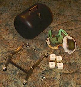
Image #1
![]() This image
shows the finished and painted, inside and out, freon tank shell. I
have
completed the bending and welding together of the forge support
structure,
and the adjustable feet are in place temporarily. It is still
unpainted.
To the right of the leg structure are the four 1" kiln shelf supports
which
hold the floor slab in place. Note the holes in the posts that allow
them
to be placed over the bolts that hold on the leg structure. I also
filled
each one with "Tenax" refractory to stabilize them from movement during
the
placement of the Kaowool. The ends of the Freon tank are in the picture
to
show what they looked like after cutting them out with the torch. I
used
a 4" angle grinder to true up the holes. You can do as well with a file
if
no grinder is available. Be very
careful while cutting
the ends out with your torch because the green paint on the tank
creates
a highly toxic smoke when it burns. Also, the burning of any
residual
Freon will create deadly phosgene gas. Wear a carbon cartridge
respirator,
or it may lay you low with just one breath! Be very careful.
This image
shows the finished and painted, inside and out, freon tank shell. I
have
completed the bending and welding together of the forge support
structure,
and the adjustable feet are in place temporarily. It is still
unpainted.
To the right of the leg structure are the four 1" kiln shelf supports
which
hold the floor slab in place. Note the holes in the posts that allow
them
to be placed over the bolts that hold on the leg structure. I also
filled
each one with "Tenax" refractory to stabilize them from movement during
the
placement of the Kaowool. The ends of the Freon tank are in the picture
to
show what they looked like after cutting them out with the torch. I
used
a 4" angle grinder to true up the holes. You can do as well with a file
if
no grinder is available. Be very
careful while cutting
the ends out with your torch because the green paint on the tank
creates
a highly toxic smoke when it burns. Also, the burning of any
residual
Freon will create deadly phosgene gas. Wear a carbon cartridge
respirator,
or it may lay you low with just one breath! Be very careful.
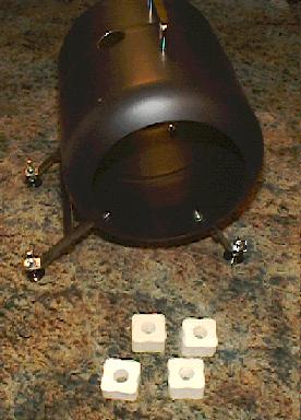
Image #2
![]() Here the
forge
shell is temporarily in place on the legs. You can see the bolts over
which
the four kiln shelf posts, shown in front, will be placed. The bolts
are
not level horizontally, but due to the width of the posts this presents
no
problem in leveling the floor slab. The handle is in place, and the
burner
penetration hole is finished. Notice that the legs on the left side are
longer
than the ones on the right. This was done to support the additional
weight
of the burner which is mounted on, and projects to, the left side. This
arrangement provides a very stable forge while in use.
Here the
forge
shell is temporarily in place on the legs. You can see the bolts over
which
the four kiln shelf posts, shown in front, will be placed. The bolts
are
not level horizontally, but due to the width of the posts this presents
no
problem in leveling the floor slab. The handle is in place, and the
burner
penetration hole is finished. Notice that the legs on the left side are
longer
than the ones on the right. This was done to support the additional
weight
of the burner which is mounted on, and projects to, the left side. This
arrangement provides a very stable forge while in use.
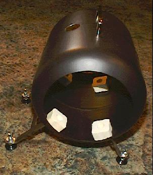
Image #3
![]() This shows
the forge shell with kiln shelf posts in place prior to filling with
Tenax
refractory. After filling them with Tenax they can be adjusted in their
location
a small amount to obtain the best fit for the floor
slab and then
allowed to cure. Any kind of mastic refractory will work as well, or
perhaps
even better, than Tenax.
This shows
the forge shell with kiln shelf posts in place prior to filling with
Tenax
refractory. After filling them with Tenax they can be adjusted in their
location
a small amount to obtain the best fit for the floor
slab and then
allowed to cure. Any kind of mastic refractory will work as well, or
perhaps
even better, than Tenax.
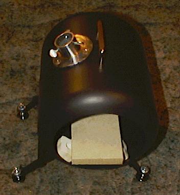
Image #4
![]() This image
clearly shows how the slab supports are not level, but the width of the
support
posts allow the floor slab to be levelled perfectly. I was able to
adjust
the set of supports on the right to be further to the right when I
filled
each hole with Tenax. The leg structure has now been painted.
You may
certainly modify the leg design in any manor that suits you. The burner
support
collar is done and in place but still unpainted. I used a fine paste
refractory
to seat it to the shell as I bolted it in place. Be sure the refractory
is
completely dry prior to firing up the forge. I didn't, and it bubbled
out
moisture, ruining my paint in that area. The area around the burner
mounting
had to be cleaned and later repainted.
This image
clearly shows how the slab supports are not level, but the width of the
support
posts allow the floor slab to be levelled perfectly. I was able to
adjust
the set of supports on the right to be further to the right when I
filled
each hole with Tenax. The leg structure has now been painted.
You may
certainly modify the leg design in any manor that suits you. The burner
support
collar is done and in place but still unpainted. I used a fine paste
refractory
to seat it to the shell as I bolted it in place. Be sure the refractory
is
completely dry prior to firing up the forge. I didn't, and it bubbled
out
moisture, ruining my paint in that area. The area around the burner
mounting
had to be cleaned and later repainted.
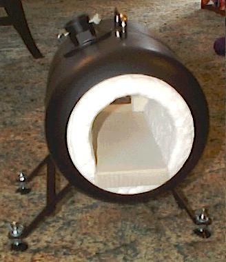
Image #5
![]() It is
starting
to look like a forge. The two layers of Kaowool are in place, and the
floor
slab is seated on the kiln shelf posts. Despite the image, the forge
floor
is level. The burner mount has been painted, and you
can also see
the square socket I have brazed on to the burner mounting flange.
(Please see the alternative socket I have
a link to under
image #9) It will be used later for the support arm that will
hold the
front Kaowool board wall in place, but will allow easy removal for
changing
floor protection plates used for forge welding, or for maintainence of
the
interior. The square socket was forged from a piece of 5/8" ID pipe. If
you
are careful you can end up with a square tube that looks as though it
was
machined, and not forged, after you have ground the surface and filed
the
scale from the interior. You can just see the corner of the rear
Kaowool
board wall which has been installed and is held in place by the
squeezing
action of the Kaowool....a friction fit. I cut it about 1/4" wider and
higher
than the interior surface dimensions of the Kaowool......see below. It
fits
very much like the ends of a wooden keg, and is very solid. Use a
smooth
thin knife blade, such as a butter knife, to act like a shoe-horn to
work
the piece into place. You can depress the Kaowool by reaching in from
the
other end too, and that is of great help in getting the piece into
place.
Once its all coated with ITC-100, and has been fired for a period of
time,
the Kaowool will take a "set" and the end wall will be very secure,
even
if bumped accidentally with the end of a long piece of iron.
It is
starting
to look like a forge. The two layers of Kaowool are in place, and the
floor
slab is seated on the kiln shelf posts. Despite the image, the forge
floor
is level. The burner mount has been painted, and you
can also see
the square socket I have brazed on to the burner mounting flange.
(Please see the alternative socket I have
a link to under
image #9) It will be used later for the support arm that will
hold the
front Kaowool board wall in place, but will allow easy removal for
changing
floor protection plates used for forge welding, or for maintainence of
the
interior. The square socket was forged from a piece of 5/8" ID pipe. If
you
are careful you can end up with a square tube that looks as though it
was
machined, and not forged, after you have ground the surface and filed
the
scale from the interior. You can just see the corner of the rear
Kaowool
board wall which has been installed and is held in place by the
squeezing
action of the Kaowool....a friction fit. I cut it about 1/4" wider and
higher
than the interior surface dimensions of the Kaowool......see below. It
fits
very much like the ends of a wooden keg, and is very solid. Use a
smooth
thin knife blade, such as a butter knife, to act like a shoe-horn to
work
the piece into place. You can depress the Kaowool by reaching in from
the
other end too, and that is of great help in getting the piece into
place.
Once its all coated with ITC-100, and has been fired for a period of
time,
the Kaowool will take a "set" and the end wall will be very secure,
even
if bumped accidentally with the end of a long piece of iron.
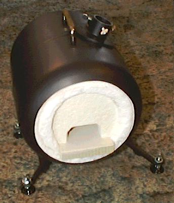
Image #6
![]() This image
shows the Kaowool back wall in place in the back of the forge. The
opening
is primarily an exhaust port, but will allow longer pieces of steel to
protrude
through when necessary.
This image
shows the Kaowool back wall in place in the back of the forge. The
opening
is primarily an exhaust port, but will allow longer pieces of steel to
protrude
through when necessary.
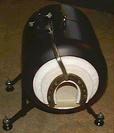
Image #7
![]() Well, its
almost
done. I have used a small horseshoe for the mounting bracket to support
the
front Kaowool board closure. The Kaowool board has been taper cut to
fit
into the opening of the forge like a cork in a bottle, and is held on
to
the horseshoe by four stainless wood screws. It is difficult
to see
the detail of the support arm arrangement, but the horseshoe is
supported
by a forged piece of 3/8" square section which sockets into a forged
square
socket that has a thumbscrew lock. There is more to it than I have
described,
and I will attempt to clarify it with the image below. It is fully
adjustable,
and will release the front Kaowool closure for instant removal
with
just a twist of the thumb screw. The forge still has to have its new
ironwork
painted, the ITC-100 interior coating applied, and it will then be
complete
and ready for service.
Well, its
almost
done. I have used a small horseshoe for the mounting bracket to support
the
front Kaowool board closure. The Kaowool board has been taper cut to
fit
into the opening of the forge like a cork in a bottle, and is held on
to
the horseshoe by four stainless wood screws. It is difficult
to see
the detail of the support arm arrangement, but the horseshoe is
supported
by a forged piece of 3/8" square section which sockets into a forged
square
socket that has a thumbscrew lock. There is more to it than I have
described,
and I will attempt to clarify it with the image below. It is fully
adjustable,
and will release the front Kaowool closure for instant removal
with
just a twist of the thumb screw. The forge still has to have its new
ironwork
painted, the ITC-100 interior coating applied, and it will then be
complete
and ready for service.
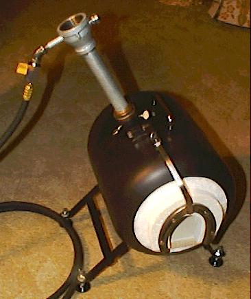
Image #8
![]() This
image shows the support bracket, and its attachment
to the burner
support collar, along with the "EZ-Burner" locked into position.
The
burner collar has a precision forged square socket, made from a 5/8"
diameter
steel pipe, and attached to the bracket collar with brazing.
It is already
painted black in this image. It was forged to exactly engage the 3/8"
square
rod that is socketed into it. The 3/8"rod is bent 90
degrees,
and the other end is brazed into the back end of a second, and longer,
precision
forged square section tube that has a thumb screw on its end to the
right.
The rest of the bracket mechanism is clearly shown in the image. The
attachment
to the horseshoe is a weldment, as I was concerned that it might get
hot
enough in that location to melt a brazed connection. When
making the
precision forged sockets I forged them slightly undersized, about two
thousandths, and then filed and polished the surfaces of the 3/8" rod,
and
interior of the socket, to perfectly engage without play. Doing it this
way
resulted in a connection that has no scale in it and is perfectly
smooth.
Most casual observers would think it was machined instead of forged.
Probably the most difficult part of the entire bracket was
getting the
position of the horseshoe into exact alignment in all three axes. I
found
that to try to get it exact prior to welding was impossible. I simply
welded
it, prepositioned as closely as possible, and then tweaked the
alignment
in the post vise while cold.
This
image shows the support bracket, and its attachment
to the burner
support collar, along with the "EZ-Burner" locked into position.
The
burner collar has a precision forged square socket, made from a 5/8"
diameter
steel pipe, and attached to the bracket collar with brazing.
It is already
painted black in this image. It was forged to exactly engage the 3/8"
square
rod that is socketed into it. The 3/8"rod is bent 90
degrees,
and the other end is brazed into the back end of a second, and longer,
precision
forged square section tube that has a thumb screw on its end to the
right.
The rest of the bracket mechanism is clearly shown in the image. The
attachment
to the horseshoe is a weldment, as I was concerned that it might get
hot
enough in that location to melt a brazed connection. When
making the
precision forged sockets I forged them slightly undersized, about two
thousandths, and then filed and polished the surfaces of the 3/8" rod,
and
interior of the socket, to perfectly engage without play. Doing it this
way
resulted in a connection that has no scale in it and is perfectly
smooth.
Most casual observers would think it was machined instead of forged.
Probably the most difficult part of the entire bracket was
getting the
position of the horseshoe into exact alignment in all three axes. I
found
that to try to get it exact prior to welding was impossible. I simply
welded
it, prepositioned as closely as possible, and then tweaked the
alignment
in the post vise while cold.
Note: To forge a square cross-section out of a round pipe, do not use a square mandrel, but simply work it hot on alternate sides, much as you would to draw out a long square taper on a bar. It will automatically form into a perfect square shape inside and out. It is very surprising the first time you do one of these forgings how perfectly it will come out if your hammer work is carefully done. If you have started with the correct size pipe it will end up almost perfect, with flat interior faces, square interior and exterior corners, and a uniform thickness all around. If the pipe you started with is too large, the extra metal will cause the interior surfaces to bulge inward, and "cold shuts" will form in the four interior corners, greatly weakening the forging. Throw it out and try again with a smaller pipe. Be very careful when quenching pipe. Scalding steam and boiling water often come shooting out the top of the pipe, and can hit you squarely in the face or burn your arm. Always keep it aimed well away from you! Pipe is very dangerous to quench. You would be well advised to just allow it to cool in the air if you are not experienced in this kind of work.
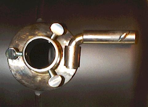
Alternative Burner Mounting Bracket Design - Image 9a
*This alternative burner mounting flange is one that I installed on a forge I build for another smith. It has several modifications that make it more functional, and actually easier to build, because you will not have to forge a pipe into a square tube. I used a 3/8" diameter pipe that I ground flat on one side for brazing to a flat that I filed in the mounting bracket flange to match. I used a short length of 3/8" hot rolled rod bent into a 90 degree elbow to socket into the 1" length of pipe mounted on the flange. On the other end of the 90 degree, 3/8" rod, I brazed on another straight length of 3/8" pipe in which I drilled and tapped a 1/4"- 20 hole to accept the locking thumb screw. Making it this way will allow full motion up and down, as well as rotational, so that the front Kaowool board door panel, which is secured with this fitting, will fit more easily and precisely. Finding 3/8" black iron pipe is not an easy matter, so I finally bought a couple of feet of 3/8" galvanized pipe and burned off the zinc coating in the forge....don't breath the smoke! I was quite pleased with the tolerances of the pipe, and hot rolled rod. Once the weld rib was removed from the interior of the pipe the fit was quite tight and secure. I would strongly recommend this method over my original burner mounting bracket method pictured above, although successfully forging a perfect square section out of round pipe will make your day. :-)
![]() The
rather
poor image above shows the curing of the forge, its first firing with
everything
in place. The Kaowool board closures are blackened from their initial
burn
off of contaminants, but show the nice clean white color slowly
replacing
the black discoloration. I ran the forge at a low pressure for about 15
minutes
to drive off most of the water from the ITC-100 application the
previous
day. Once the steam quit coming off, I cranked it up to an intense
heat,
40 psi, for about 30 minutes to see what would happen. It worked very
well,
so it is all done now except for some minor repainting where the burner
mounting
paint job was damaged during its initial firing a week earlier.
The
horseshoe was quickly blued by the heat, so may actually scale during
extended
use, although I will probably never run it at the intense heat it is
experiencing
in this image. The gas pressure was about 40 psi, and
normally it
would never be run greater than about 8 psi, more likely 4-5 psi. Well,
that
is the end of the project. Now I will enjoy using this beautiful new
tool.
Thank you for following along in its construction. :-)
The
rather
poor image above shows the curing of the forge, its first firing with
everything
in place. The Kaowool board closures are blackened from their initial
burn
off of contaminants, but show the nice clean white color slowly
replacing
the black discoloration. I ran the forge at a low pressure for about 15
minutes
to drive off most of the water from the ITC-100 application the
previous
day. Once the steam quit coming off, I cranked it up to an intense
heat,
40 psi, for about 30 minutes to see what would happen. It worked very
well,
so it is all done now except for some minor repainting where the burner
mounting
paint job was damaged during its initial firing a week earlier.
The
horseshoe was quickly blued by the heat, so may actually scale during
extended
use, although I will probably never run it at the intense heat it is
experiencing
in this image. The gas pressure was about 40 psi, and
normally it
would never be run greater than about 8 psi, more likely 4-5 psi. Well,
that
is the end of the project. Now I will enjoy using this beautiful new
tool.
Thank you for following along in its construction. :-)
Ron
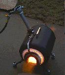
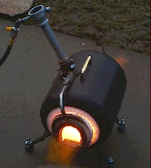
A Comment After Using the Forge for a Month
![]() I have now
been running this forge for extended periods, as much as 8 hours at a
time,
for over a month. The horseshoe, which I painted with a high
temperature
black paint, shows no signs of distress. The whole forge seems very
stable,
with no heat damage to the paint job visible anywhere. It appears that
the
shell and metal fittings will hold up well during extended periods of
use
far into the future. The only negative comment I would make, is that
the
opening in the front is quite small for using some of my larger tongs.
I
have to be very careful when placing or withdrawing my irons so as not
to
damage the Kaowool board, or the ITC-100 coating on it. Otherwise, it
is
a joy to use, and quickly cools off enough to put away. I want to
stress
however that this forge was not intended to be a primary workhorse
forge,
but to be used only for that occasional quick heat that comes along
when
you really don't wish to heat up your much bigger main forge. An
exception
to this might be if you want to forge blades.
I have now
been running this forge for extended periods, as much as 8 hours at a
time,
for over a month. The horseshoe, which I painted with a high
temperature
black paint, shows no signs of distress. The whole forge seems very
stable,
with no heat damage to the paint job visible anywhere. It appears that
the
shell and metal fittings will hold up well during extended periods of
use
far into the future. The only negative comment I would make, is that
the
opening in the front is quite small for using some of my larger tongs.
I
have to be very careful when placing or withdrawing my irons so as not
to
damage the Kaowool board, or the ITC-100 coating on it. Otherwise, it
is
a joy to use, and quickly cools off enough to put away. I want to
stress
however that this forge was not intended to be a primary workhorse
forge,
but to be used only for that occasional quick heat that comes along
when
you really don't wish to heat up your much bigger main forge. An
exception
to this might be if you want to forge blades.
Thank You For the Visit
![]() Thank you
for
visiting this page. I hope you find it of help in your own forge
construction.
Remember, I can no longer provide help or support in the construction
of
my burners or forges. If you want to contact me for another reason you
may
do so from the link at the bottom of this page. Thank you.
Thank you
for
visiting this page. I hope you find it of help in your own forge
construction.
Remember, I can no longer provide help or support in the construction
of
my burners or forges. If you want to contact me for another reason you
may
do so from the link at the bottom of this page. Thank you.
Return to my Forge and Burner Design Page
Return
to my Forge and Foundry Page
Page By: Ron Reil
Updated: 3 Mar 06
©Golden Age Forge
