

©Golden Age Forge

The Full Site Map - Lists All Pages on This Site
Contact me by phone: (208) 462-4028
Note: Due to spam problems I no longer post my e-mail address.
Materials and Hardware Sources
Refractories, Burner Flares, & T-Rex Burners
Sources For Refractory Materials
![]() A Word
to Potential
Advertisers: I do not carry banners,
flashing icons, or other
eye catching low class graphics to advertise products on my pages. All
commercial
links posted here are on my page for the convenience of the persons
using
my page, not for economic gain of the business or me. I receive no
payment
for any links or comments made here. My comments are honest evaluations
of
the source to make decision making easier for my page users. If you
wish
to add your link to my "Sources" section, it must be in keeping with
the
purpose of this section, and
if accepted,
it will not have any logos, banners, or icons, other than those already
present
in this section. If you would like to discuss a link please phone me at
(208)
462-4028.
Warning, I
receive many requests, but accept
very few.
A Word
to Potential
Advertisers: I do not carry banners,
flashing icons, or other
eye catching low class graphics to advertise products on my pages. All
commercial
links posted here are on my page for the convenience of the persons
using
my page, not for economic gain of the business or me. I receive no
payment
for any links or comments made here. My comments are honest evaluations
of
the source to make decision making easier for my page users. If you
wish
to add your link to my "Sources" section, it must be in keeping with
the
purpose of this section, and
if accepted,
it will not have any logos, banners, or icons, other than those already
present
in this section. If you would like to discuss a link please phone me at
(208)
462-4028.
Warning, I
receive many requests, but accept
very few.
![]() I get many
e-mails asking
where to obtain the Kaowool, ITC-100, propane regulators, and other
materials
necessary in forge construction. Here are some sources for these
materials,
and others, that you may use to obtain needed parts and materials.
Jay Hayes
and
Rex Price
have refractory materials
available at a very good prices, and much lower than available in most
places.
Jay has a web
page which
is under construction that you may wish to visit too, and is worth your
time
to do so, as he has a lovely place. Rex Price also produces and sells
the
finest and hottest ventouri burners made in the world at this time. You
may
want to visit
Rex's web page
and look at his burner selection instead of building your own. These
are
hotter then anything you can build on your own. Thanks.
I get many
e-mails asking
where to obtain the Kaowool, ITC-100, propane regulators, and other
materials
necessary in forge construction. Here are some sources for these
materials,
and others, that you may use to obtain needed parts and materials.
Jay Hayes
and
Rex Price
have refractory materials
available at a very good prices, and much lower than available in most
places.
Jay has a web
page which
is under construction that you may wish to visit too, and is worth your
time
to do so, as he has a lovely place. Rex Price also produces and sells
the
finest and hottest ventouri burners made in the world at this time. You
may
want to visit
Rex's web page
and look at his burner selection instead of building your own. These
are
hotter then anything you can build on your own. Thanks.
![]() Here is another
location
that you may use, but you will have to phone this company at your own
expense.
This is "The Potter's Center"
here in Boise, where I purchase
my supplies when I need them immediately. They have Kaowool board, high
alumina
kiln shelves in various dimensions shapes and thicknesses, ITC-100,
kiln
shelf posts, and many other useful materials and items, including
pyrometers.
They will be glad to mail an order to you, but they do not have a
catalog.
You will have to work out your order over the phone. Their prices are
high
for some items and very reasonable for others. Phone (208) 378-1112, or
Fax
(208) 378-8881. Scott Brown, the owner, also has the following 800
number
on his card, but I don't know that it is still in service, try
1-800-498-1126.
Here is another
location
that you may use, but you will have to phone this company at your own
expense.
This is "The Potter's Center"
here in Boise, where I purchase
my supplies when I need them immediately. They have Kaowool board, high
alumina
kiln shelves in various dimensions shapes and thicknesses, ITC-100,
kiln
shelf posts, and many other useful materials and items, including
pyrometers.
They will be glad to mail an order to you, but they do not have a
catalog.
You will have to work out your order over the phone. Their prices are
high
for some items and very reasonable for others. Phone (208) 378-1112, or
Fax
(208) 378-8881. Scott Brown, the owner, also has the following 800
number
on his card, but I don't know that it is still in service, try
1-800-498-1126.
![]() I have to thank
Matt
Bomba for this link.
Clayartcenter.com
is a one stop
pottery supply center, and has a good selection of all the needed
components,
refractories, and other items that you might need to build your melting
furnace,
forge, kiln, or heat treating oven. Their prices seem to be in line
with
the going rates elsewhere. Their online catalog is a little difficult
to
find, but if you go to the lower left corner of the page there is a box
with
links to various items. If you click on any of the items listed, you
will
be taken to the catalog and can easily explore from there. Check it out.
I have to thank
Matt
Bomba for this link.
Clayartcenter.com
is a one stop
pottery supply center, and has a good selection of all the needed
components,
refractories, and other items that you might need to build your melting
furnace,
forge, kiln, or heat treating oven. Their prices seem to be in line
with
the going rates elsewhere. Their online catalog is a little difficult
to
find, but if you go to the lower left corner of the page there is a box
with
links to various items. If you click on any of the items listed, you
will
be taken to the catalog and can easily explore from there. Check it out.
![]() Here is one more
useful
link. If you are involved with foundry work, this is a must have link.
It
is also of value for blacksmiths, or anyone who uses high temperature
products.
They carry refractory products, ITC-100 in its various forms, and a lot
more.
Budget
Casting Supply is
well worth a look. You can e-mail
Paul if you have a question about a product too.
Here is one more
useful
link. If you are involved with foundry work, this is a must have link.
It
is also of value for blacksmiths, or anyone who uses high temperature
products.
They carry refractory products, ITC-100 in its various forms, and a lot
more.
Budget
Casting Supply is
well worth a look. You can e-mail
Paul if you have a question about a product too.
![]() I have no other sources
than those listed above,
so please don't e-mail me with a request for additional
sources. I
suggest you check locally in your area if the above sources are not
convenient
for you.
I have no other sources
than those listed above,
so please don't e-mail me with a request for additional
sources. I
suggest you check locally in your area if the above sources are not
convenient
for you.
![]() A Note About
ITC-100 and
Kaowool:
ITC-100 is more than just a ceramic
wool stabilizer. It is an infrared reflector that reradiates up to 98%
of
the heat that strikes it back into the forge chamber. This will heat
your
iron faster, and will act like an additional inch of Kaowool, providing
lower
shell temperature and better fuel economy, as much as 30% better in
independent
tests. It will also stabilize the Kaowool so that you don't
have dangerous
ceramic fibers in the forge exhaust. It will last almost forever if it
is
not damaged through mechanical injury by you or others using your
forge.
Even though it is semi expensive, it is well worth the cost as it will
repay
you in various ways, directly and indirectly, very quickly. It may be
used
on any kind of forge chamber surface, not just Kaowool. Also, if you
have
metal surfaces in the forge, there are special undercoatings available
to
bond the ITC-100 to the smooth metallic surface. I should add that this
material
is not useful in a coal forge.
A Note About
ITC-100 and
Kaowool:
ITC-100 is more than just a ceramic
wool stabilizer. It is an infrared reflector that reradiates up to 98%
of
the heat that strikes it back into the forge chamber. This will heat
your
iron faster, and will act like an additional inch of Kaowool, providing
lower
shell temperature and better fuel economy, as much as 30% better in
independent
tests. It will also stabilize the Kaowool so that you don't
have dangerous
ceramic fibers in the forge exhaust. It will last almost forever if it
is
not damaged through mechanical injury by you or others using your
forge.
Even though it is semi expensive, it is well worth the cost as it will
repay
you in various ways, directly and indirectly, very quickly. It may be
used
on any kind of forge chamber surface, not just Kaowool. Also, if you
have
metal surfaces in the forge, there are special undercoatings available
to
bond the ITC-100 to the smooth metallic surface. I should add that this
material
is not useful in a coal forge.
![]() Kaowool comes in two
temperature ranges. One is about 2300 degrees, and the other 2700
degrees.
Although your forge should run up near 2700 degrees, or hotter, you may
use
the lower temperature Kaowool if its fully coated with ITC-100. The
ITC-100
should reflect the heat enough to prevent problems due to the lower
temperature
range of the material. I would suggest you use the higher range Kaowool
however,
unless you are unable to obtain it from your supplier. Jay Hayes has
both
available, so specify which kind you want when ordering. The higher
temperature
Kaowool is more expensive as would be expected. You should use ITC-100
on
the Kaowool whichever kind you use.
Kaowool comes in two
temperature ranges. One is about 2300 degrees, and the other 2700
degrees.
Although your forge should run up near 2700 degrees, or hotter, you may
use
the lower temperature Kaowool if its fully coated with ITC-100. The
ITC-100
should reflect the heat enough to prevent problems due to the lower
temperature
range of the material. I would suggest you use the higher range Kaowool
however,
unless you are unable to obtain it from your supplier. Jay Hayes has
both
available, so specify which kind you want when ordering. The higher
temperature
Kaowool is more expensive as would be expected. You should use ITC-100
on
the Kaowool whichever kind you use.
Do You Need a Premade Burner Flare?
![]() The following
four factors
are, in my opinion, what a flared nozzle does to contribute to burner
performance, and why you should use one of your own making, or one of
the
stainless flares offered here.
The following
four factors
are, in my opinion, what a flared nozzle does to contribute to burner
performance, and why you should use one of your own making, or one of
the
stainless flares offered here.
1) The flared nozzle acts like the "impedance matching device" found on radio transmission antennas. It creates a "pressure transition" to balance the internal pressure of the burner tube to the lower pressure of the forge chamber atmosphere.
2) It slows the gas stream to a velocity below the burn velocity...its flame holding and stabilizing function.
3) It creates a low pressure in the nozzle step that, in effect, invites more gas down the burner tube, allowing a slightly greater output than would occur without it. This factor is not proven or provable with our crude testing equipment, but I can clearly see its contribution in my mind.
4) The last function is to initiate the burn earlier so as to prevent the injection of cold gasses and free oxygen into the chamber of the forge or furnace....the result is a hotter chamber and less, or no, scaling.
![]() If
you would like to buy premade burner flares that
have a perfect
1:12 taper, and made of stainless steel no less, there is now a source.
Most
of the problems that I deal with when helping guys with burner problems
relate
to the rate of flare of the burner flares that they put on their
burners.
If the flare is not made correctly the burner will not function
correctly.
I was astounded when Larry
Zoeller
sent me one of his "press formed" stainless steel flares to try. I
removed
one of the old forged flares from the number one burner on my four
burner
forge and installed Larry's stainless flare. My old mild steel flare
came
off in fragments, as it had totally corroded through in only two years
of
use. The best I had been able to do for "idle" pressure with my old
forged
flare was 2 psi. Below that the flame would start to pulsate or huff.
When
I put Larry's flare on the burner it easily held the flame steady all
the
way down to a little below 1 psi! His flare just doubled the "idle"
economy
of my forge! I have ordered 7 more from Larry, they are that good. I
can
certainly make my own flares, but to obtain the precision that Larry
has
achieved I would have to set up a hydraulic press as he has
done.
If
you would like to buy premade burner flares that
have a perfect
1:12 taper, and made of stainless steel no less, there is now a source.
Most
of the problems that I deal with when helping guys with burner problems
relate
to the rate of flare of the burner flares that they put on their
burners.
If the flare is not made correctly the burner will not function
correctly.
I was astounded when Larry
Zoeller
sent me one of his "press formed" stainless steel flares to try. I
removed
one of the old forged flares from the number one burner on my four
burner
forge and installed Larry's stainless flare. My old mild steel flare
came
off in fragments, as it had totally corroded through in only two years
of
use. The best I had been able to do for "idle" pressure with my old
forged
flare was 2 psi. Below that the flame would start to pulsate or huff.
When
I put Larry's flare on the burner it easily held the flame steady all
the
way down to a little below 1 psi! His flare just doubled the "idle"
economy
of my forge! I have ordered 7 more from Larry, they are that good. I
can
certainly make my own flares, but to obtain the precision that Larry
has
achieved I would have to set up a hydraulic press as he has
done.
![]() If
you would like to obtain some of these superb flares, contact Larry at
the
address shown below, or at his e-mail address. I am sure you will be
very
satisfied with the results of your purchase. You may initially think
that
his price of $6.50, plus shipping, for a burner flare is steep, but
remember
that he not only makes them from stainless steel, but they are drilled
and
tapped, and come with two stainless set screws installed also. They are
ready
to just tighten into place on your burner. BTW, I get no payment of any
kind
for this "add." I just think that these flares meet a big need out
there
in the metalworking field and should be made available to the forge and
foundry
community. Please
be aware that
these flares can melt and deform
if used on the Micromongo
Burner when its run at high gas pressures. In the case cited in the
linked
document, Fred was running them at 25
psi.
If
you would like to obtain some of these superb flares, contact Larry at
the
address shown below, or at his e-mail address. I am sure you will be
very
satisfied with the results of your purchase. You may initially think
that
his price of $6.50, plus shipping, for a burner flare is steep, but
remember
that he not only makes them from stainless steel, but they are drilled
and
tapped, and come with two stainless set screws installed also. They are
ready
to just tighten into place on your burner. BTW, I get no payment of any
kind
for this "add." I just think that these flares meet a big need out
there
in the metalworking field and should be made available to the forge and
foundry
community. Please
be aware that
these flares can melt and deform
if used on the Micromongo
Burner when its run at high gas pressures. In the case cited in the
linked
document, Fred was running them at 25
psi.
Larry Zoeller
4312 Lahnna Dr.
Louisville, KY 40216
USA
(502) 361-0706
![]() Visit Larry's
Burner
Flare
Page. You can see what they look like, and Larry has a price
sheet with
details there as well.
Visit Larry's
Burner
Flare
Page. You can see what they look like, and Larry has a price
sheet with
details there as well.
Premade Burners Are Now Available
The "T-Rex" Family of Burners
![]() There is now a
superb
new premade burner series available for those who do not want to build
their
own, or for those who want the ultimate in both quality and BTU output.
The
T-Rex is a turned, milled, and tuned hybrid designed jet ejector burner
which has to be experienced to be believed. For a complete
description
see the "T-Rex Burner" page.
There is now a
superb
new premade burner series available for those who do not want to build
their
own, or for those who want the ultimate in both quality and BTU output.
The
T-Rex is a turned, milled, and tuned hybrid designed jet ejector burner
which has to be experienced to be believed. For a complete
description
see the "T-Rex Burner" page.
![]() Another
burner that you may want to consider, and part of the
developing T-Rex
family of burners, is the "Shorty Burner." This is a
miniturized T-Rex, and has
applications in places
where the T-Rex may not fit, or where this reduced sized burner would
be
more convenient. I have a Shorty
Burner Page available
if you would like more information.
Another
burner that you may want to consider, and part of the
developing T-Rex
family of burners, is the "Shorty Burner." This is a
miniturized T-Rex, and has
applications in places
where the T-Rex may not fit, or where this reduced sized burner would
be
more convenient. I have a Shorty
Burner Page available
if you would like more information.
![]() You may
go directly to
Rex's own Burner
page if you wish. He has a troubleshooting page, and a price
sheet there,
as well as a short description of the burners he presently is
producing,
which now include several much larger burners than I have listed here.
I
will not keep his full listing of burners updated on this page now that
he
has this information available for you on his page. The
descriptions
for the T-Rex and Shorty burner I have here are more complete than what
you
will find on Rex's site, so you may want to read these first, and then
link
to his site. I have links to his site at the end of each of the above
linked
pages for your convenience.
You may
go directly to
Rex's own Burner
page if you wish. He has a troubleshooting page, and a price
sheet there,
as well as a short description of the burners he presently is
producing,
which now include several much larger burners than I have listed here.
I
will not keep his full listing of burners updated on this page now that
he
has this information available for you on his page. The
descriptions
for the T-Rex and Shorty burner I have here are more complete than what
you
will find on Rex's site, so you may want to read these first, and then
link
to his site. I have links to his site at the end of each of the above
linked
pages for your convenience.
![]() I am very pleased
to
be able to offer you a very convenient BTU output calculator. It will
allow
you to calculate as closely as possible how much heat energy you are
delivering
out the nozzle of your burner, given the gas pressure you are using,
and
orifice, jet, diameter of the burner. This very fine program was
created
by Thomas Vincent.
It is in Exel format,
so you will have to have Microsoft Excel on your computer to be able to
use
this program. I have it available here in several forms. You may
download
the zipped file, which includes the "Orifice Document", the "Calculator
Instruction Document", and the "BTU Calculator" program. You can then
unzip
it and use it as needed. Or, you can use it directly by simply clicking
on
the "BTU Output Calculator" file link. Again, to use this calculator
your
system will have to have Microsoft Office installed on it in order to
be
able to open these Word and Excel documents. If you download the files
to
use on your own system, be sure you read the instruction file first in
order
to prevent damage to the Calculator file through improper number input.
The
Calculator program requires entry of your burner "orifice" diameter in
decimal
form. I have the conversions from drill # to decimal diameter available
in
my FAQ.
You are
free to distribute this calculator file so long as you maintain the
source
information, my site, with the file and leave the authors name on all
documants
as they are provided to you here. Tom did a lot of work to provide you
with
this valuable tool, free of charge, so he deserves to be given credit
for
his work. Thanks.
I am very pleased
to
be able to offer you a very convenient BTU output calculator. It will
allow
you to calculate as closely as possible how much heat energy you are
delivering
out the nozzle of your burner, given the gas pressure you are using,
and
orifice, jet, diameter of the burner. This very fine program was
created
by Thomas Vincent.
It is in Exel format,
so you will have to have Microsoft Excel on your computer to be able to
use
this program. I have it available here in several forms. You may
download
the zipped file, which includes the "Orifice Document", the "Calculator
Instruction Document", and the "BTU Calculator" program. You can then
unzip
it and use it as needed. Or, you can use it directly by simply clicking
on
the "BTU Output Calculator" file link. Again, to use this calculator
your
system will have to have Microsoft Office installed on it in order to
be
able to open these Word and Excel documents. If you download the files
to
use on your own system, be sure you read the instruction file first in
order
to prevent damage to the Calculator file through improper number input.
The
Calculator program requires entry of your burner "orifice" diameter in
decimal
form. I have the conversions from drill # to decimal diameter available
in
my FAQ.
You are
free to distribute this calculator file so long as you maintain the
source
information, my site, with the file and leave the authors name on all
documants
as they are provided to you here. Tom did a lot of work to provide you
with
this valuable tool, free of charge, so he deserves to be given credit
for
his work. Thanks.
![]() BTW, I am able to
open
these files with Office 97, so if you have Office 97, or above, you
should
be able to use this program without any problem. Due to the size of the
Orifice
document, it is advised that you download the zipped file instead of
using
these files directly off my site.
BTW, I am able to
open
these files with Office 97, so if you have Office 97, or above, you
should
be able to use this program without any problem. Due to the size of the
Orifice
document, it is advised that you download the zipped file instead of
using
these files directly off my site.
BTU Calculator Instructions Document
Download All Three Documents in Zipped Format
Will Gas Forges Weld?....an E-mail
![]() I have run into two
areas of ignorance that I have continually to fight, even on
"theforge".
One concerns the ability of a gas forge to forge weld. This is
certainly
not a problem within the members of theforge, but the second is. I was
told
by a smith on theforge that "everyone knows that gas forges can weld,
and
have for years", and that certainly is not true. I have posted an
e-mail
I received that addresses both of these points. I am posting this to
show
that there is still a lot of ignorance out there that needs to be
addressed.
We, as brothers in this craft, all need to tend to these issues when
the
opportunity is presented. Most certainly the gentleman who sent me the
e-mail
is not one who needs educating. He is anything but ignorant in these
matters.
I am posting his e-mail
for your interest. He
was kind enough to give permission for me to post this communication.
Thank
you Adam.
I have run into two
areas of ignorance that I have continually to fight, even on
"theforge".
One concerns the ability of a gas forge to forge weld. This is
certainly
not a problem within the members of theforge, but the second is. I was
told
by a smith on theforge that "everyone knows that gas forges can weld,
and
have for years", and that certainly is not true. I have posted an
e-mail
I received that addresses both of these points. I am posting this to
show
that there is still a lot of ignorance out there that needs to be
addressed.
We, as brothers in this craft, all need to tend to these issues when
the
opportunity is presented. Most certainly the gentleman who sent me the
e-mail
is not one who needs educating. He is anything but ignorant in these
matters.
I am posting his e-mail
for your interest. He
was kind enough to give permission for me to post this communication.
Thank
you Adam.
How Hot Can These Burners Get?
![]() I am very pleased
to
be able to include information about Dave Moore's ultra hot propane
fired
crucible melting furnace. Dave has been very generous with his time and
provided
me with detailed information about his melting furnace. This is such a
remarkable
achievement that I felt it deserved its own page. Please click the
image
to learn more about this exceptional piece of work.
(Note:
Dave is normally very safety minded.
Please do not ever pour hot metal without wearing proper personal
safety
equipment. As one person commented, one wandering spider in the mold
and
you will be wearing the liquid metal, and probably lose your eyes as
well.
Also, never pour metal while working over concrete. Spilled metal can
cause
the concrete to explode and blast you with molten metal, or burn down
your
shop.)
I am very pleased
to
be able to include information about Dave Moore's ultra hot propane
fired
crucible melting furnace. Dave has been very generous with his time and
provided
me with detailed information about his melting furnace. This is such a
remarkable
achievement that I felt it deserved its own page. Please click the
image
to learn more about this exceptional piece of work.
(Note:
Dave is normally very safety minded.
Please do not ever pour hot metal without wearing proper personal
safety
equipment. As one person commented, one wandering spider in the mold
and
you will be wearing the liquid metal, and probably lose your eyes as
well.
Also, never pour metal while working over concrete. Spilled metal can
cause
the concrete to explode and blast you with molten metal, or burn down
your
shop.)
Click image to visit page.
![]() I am adding this
short
paragraph at the top of this section because I consider it of great
importance.
In our development of the Mongo series of burners we discovered the
full
potential of a choke. It will enable you to run the "Reil" burner, or
any
of the Mongo series, or Side-arm burners, down to levels of gas
pressure
measured in only a few ounces. The key is to have a choke that can
totally
close the intake bell, or holes. That way you can balance the air
intake
to gas injection no matter how small the amount of gas entering the
burner.
I can now easily run my Micromongo down until the gas pressure gage
needle
is resting on the peg, and the burner still has a stable flame, no
huffing
or other problems. I estimate I am running at 1-2 ounces of gas
pressure
at this point! So to achieve the very useful low end range, that all of
these
burners can reach, use a well designed and constructed
choke. (Remember,
for a choke to be of any value, your burner must be capable
of running
in an oxidizing state, oxygen rich, when running at full pressure.)
I am adding this
short
paragraph at the top of this section because I consider it of great
importance.
In our development of the Mongo series of burners we discovered the
full
potential of a choke. It will enable you to run the "Reil" burner, or
any
of the Mongo series, or Side-arm burners, down to levels of gas
pressure
measured in only a few ounces. The key is to have a choke that can
totally
close the intake bell, or holes. That way you can balance the air
intake
to gas injection no matter how small the amount of gas entering the
burner.
I can now easily run my Micromongo down until the gas pressure gage
needle
is resting on the peg, and the burner still has a stable flame, no
huffing
or other problems. I estimate I am running at 1-2 ounces of gas
pressure
at this point! So to achieve the very useful low end range, that all of
these
burners can reach, use a well designed and constructed
choke. (Remember,
for a choke to be of any value, your burner must be capable
of running
in an oxidizing state, oxygen rich, when running at full pressure.)
![]() I was not
interested
in burner chokes when I first built my big gas forge because I operated
it
at higher pressures than I presently find necessary. As I reduced
my operating pressures down to the 1-1/2 to 5 psi range I
found that
more scale formation was occurring on my work. The answer to this
problem
is a burner choke. It allows you to tune your burner to a neutral or
reducing
flame at any given operating pressure.
I was not
interested
in burner chokes when I first built my big gas forge because I operated
it
at higher pressures than I presently find necessary. As I reduced
my operating pressures down to the 1-1/2 to 5 psi range I
found that
more scale formation was occurring on my work. The answer to this
problem
is a burner choke. It allows you to tune your burner to a neutral or
reducing
flame at any given operating pressure.
![]() The following four
choke
designs are scanned from a small forge building publication that has no
author
or publication information whatsoever. The only clue to the author's
identity
is on the front cover which is simply "JF", with a "98" under the
letters.
I could not contact the author to obtain permission, but was informed
by
the person who gave me the booklet that it was free for duplication and
distribution, so I can only assume that this use of its information
would
fall within those boundaries. If anyone knows the author I would very
much
appreciate information as to how to contact him to obtain his
permission
formally. Thank you.
The following four
choke
designs are scanned from a small forge building publication that has no
author
or publication information whatsoever. The only clue to the author's
identity
is on the front cover which is simply "JF", with a "98" under the
letters.
I could not contact the author to obtain permission, but was informed
by
the person who gave me the booklet that it was free for duplication and
distribution, so I can only assume that this use of its information
would
fall within those boundaries. If anyone knows the author I would very
much
appreciate information as to how to contact him to obtain his
permission
formally. Thank you.
![]() To use these choke
designs
it will be necessary to build your burner using the "Bordeaux
Modification"
so that you will have use of the threads in the throat of the burner
bell,
or the top surface of the bell. I would also strongly suggest that you
use
a 1-1/2" by 3/4" reducer bell instead of the 1-1/4" by 3/4" reducer
when
using a nipple section. This is due to the reduction in open intake
area
that installation of a nipple section will cause. I would also suggest
removing
any fins or flange that may be found on the interior lip of
the nipple
section used. It is important to maintain maximum gas flow through the
system
so that you can still operate at higher pressures efficiently,
therefore
choke design #4 may not be a good choice due to the considerable intake
restriction it imposes on the system.
To use these choke
designs
it will be necessary to build your burner using the "Bordeaux
Modification"
so that you will have use of the threads in the throat of the burner
bell,
or the top surface of the bell. I would also strongly suggest that you
use
a 1-1/2" by 3/4" reducer bell instead of the 1-1/4" by 3/4" reducer
when
using a nipple section. This is due to the reduction in open intake
area
that installation of a nipple section will cause. I would also suggest
removing
any fins or flange that may be found on the interior lip of
the nipple
section used. It is important to maintain maximum gas flow through the
system
so that you can still operate at higher pressures efficiently,
therefore
choke design #4 may not be a good choice due to the considerable intake
restriction it imposes on the system.
The Best (?) Burner Choke Alternative
![]() An alternative
that
is worth considering is to lock your burner jet tube down by screwing a
short
length, say 1-1/4", of nipple into the mouth of the burner bell far
enough
to contact and lock the jet tube. You will have to use a bell diameter
no
smaller than 1-1/2" to do this however to maintain enough
intake opening
area. (You may even need to use a 1-3/4" bell if you find that the back
pressure
of your forge design causes your burner to run too rich.) I recently
built
a burner this way for a forge I sold and it worked extremely well. This
makes
the construction of the burner much easier because there is no drilling
and
tapping, and it also sets up the burner with a short nipple in the bell
to
which you can add an axial choke, see
below, quite easily.
An alternative
that
is worth considering is to lock your burner jet tube down by screwing a
short
length, say 1-1/4", of nipple into the mouth of the burner bell far
enough
to contact and lock the jet tube. You will have to use a bell diameter
no
smaller than 1-1/2" to do this however to maintain enough
intake opening
area. (You may even need to use a 1-3/4" bell if you find that the back
pressure
of your forge design causes your burner to run too rich.) I recently
built
a burner this way for a forge I sold and it worked extremely well. This
makes
the construction of the burner much easier because there is no drilling
and
tapping, and it also sets up the burner with a short nipple in the bell
to
which you can add an axial choke, see
below, quite easily.
![]() One suggestion would
be to attach a small diameter cross bar across the throat of the
nipple,
and to it weld or braze a short length of all-thread which would stick
out
of the center of the opening of the burner an inch or two. You could
then
weld or braze a nut to a disk of steel that would screw down the
all-thread
and act as a finely tunable choke. The disk would not have to be as big
in
diameter as the nipple, as it only needs to restrict the air flow, not
stop
it completely. By drilling a hole through both sides of the nipple just
below
the lip it would be an easy matter to insert a cross bar that closely
fits
the holes, and to which you had already brazed on the all-thread to
form
a "T". You could then align the all-thread to the center line of the
nipple
and braze each end of the cross bar into place. It would be rock solid
and
aligned almost perfectly.
One suggestion would
be to attach a small diameter cross bar across the throat of the
nipple,
and to it weld or braze a short length of all-thread which would stick
out
of the center of the opening of the burner an inch or two. You could
then
weld or braze a nut to a disk of steel that would screw down the
all-thread
and act as a finely tunable choke. The disk would not have to be as big
in
diameter as the nipple, as it only needs to restrict the air flow, not
stop
it completely. By drilling a hole through both sides of the nipple just
below
the lip it would be an easy matter to insert a cross bar that closely
fits
the holes, and to which you had already brazed on the all-thread to
form
a "T". You could then align the all-thread to the center line of the
nipple
and braze each end of the cross bar into place. It would be rock solid
and
aligned almost perfectly.
![]() When I built the burner
I cut the section of nipple off at a point leaving about 1/4" to 3/8"
of
unthreaded section of pipe above the ends of the threads. This is where
the
cross bar would go. You would do well to try to align the cross bar
with
the jet tube below it too for better air flow characteristics. If you
drill
the two holes in the nipple first thing they can be used to place a rod
through
the nipple allowing you to screw the nipple in very tightly without
having
to use a pipe wrench which will damage the surface of the nipple. You
may
want to drill two sets of holes, one set below the other, so that you
will
have these "wrench" holes available all the time. I elected to use one
set
of hole for both purposes.
When I built the burner
I cut the section of nipple off at a point leaving about 1/4" to 3/8"
of
unthreaded section of pipe above the ends of the threads. This is where
the
cross bar would go. You would do well to try to align the cross bar
with
the jet tube below it too for better air flow characteristics. If you
drill
the two holes in the nipple first thing they can be used to place a rod
through
the nipple allowing you to screw the nipple in very tightly without
having
to use a pipe wrench which will damage the surface of the nipple. You
may
want to drill two sets of holes, one set below the other, so that you
will
have these "wrench" holes available all the time. I elected to use one
set
of hole for both purposes.
![]() Please have a look at the image
of my axial choke. It is currently mounted on my number one
burner which
has been modified to the Bordeaux mounting system. I cut two pieces of
1/4"
all-thread and brazed them together in the form of a "T". The top of
the
"T" can be inserted in the two holes in the top of the nipple and
locked
in place with a nut on one side and wing-nut on the other. I
need to
be able to remove the choke when I cover the forge up at night or the
axial
rod will poke a hole through my tarp. Just use two nuts if you don't
have
to cover the forge. I used a large diameter 1/4" washer for
the choke
disk, and brazed a quarter inch nut in its center to allow it to be
screwed
down on the vertical stem of the choke's axial rod. It is easily
adjusted
while the burner is running because it doesn't get hot. It isn't
necessary
to have a disk as large as the opening in the bell. You only need to
reduce
the air flow, not stop it. Notice that I am using the holes in the
nipple
both to tighten the nipple on the jet pipe and to mount the choke. I
love
it when things serve for more than one function. :-)
Here is
another image taken after I
converted my #2 burner
over to the axial choke design also.
Please have a look at the image
of my axial choke. It is currently mounted on my number one
burner which
has been modified to the Bordeaux mounting system. I cut two pieces of
1/4"
all-thread and brazed them together in the form of a "T". The top of
the
"T" can be inserted in the two holes in the top of the nipple and
locked
in place with a nut on one side and wing-nut on the other. I
need to
be able to remove the choke when I cover the forge up at night or the
axial
rod will poke a hole through my tarp. Just use two nuts if you don't
have
to cover the forge. I used a large diameter 1/4" washer for
the choke
disk, and brazed a quarter inch nut in its center to allow it to be
screwed
down on the vertical stem of the choke's axial rod. It is easily
adjusted
while the burner is running because it doesn't get hot. It isn't
necessary
to have a disk as large as the opening in the bell. You only need to
reduce
the air flow, not stop it. Notice that I am using the holes in the
nipple
both to tighten the nipple on the jet pipe and to mount the choke. I
love
it when things serve for more than one function. :-)
Here is
another image taken after I
converted my #2 burner
over to the axial choke design also.
![]() I now have made
some
rather important discoveries about chokes that I explained at the top
of
the Choke section. If you build an axial choke, as shown in my images,
I
have two suggestions for improvements you may want to follow. First,
increase
the size of the choke disk so it can fully close the bell. The second
suggestion
is not of great importance, but is a matter of convenience. Instead of
using
a nut to braze to the disk, use a wing-nut. That way when you screw the
disk
down very close to the bell to run your burners at very low levels, it
will
be easier to move it up again by use of the wings on the nut.
I now have made
some
rather important discoveries about chokes that I explained at the top
of
the Choke section. If you build an axial choke, as shown in my images,
I
have two suggestions for improvements you may want to follow. First,
increase
the size of the choke disk so it can fully close the bell. The second
suggestion
is not of great importance, but is a matter of convenience. Instead of
using
a nut to braze to the disk, use a wing-nut. That way when you screw the
disk
down very close to the bell to run your burners at very low levels, it
will
be easier to move it up again by use of the wings on the nut.
Note: These burners are designed by others, so if you decide to build one, please contact the designer if you encounter problems. I do not support or guarantee in any way that these burners will function as stated below. I have NO experience with any of them. My comments are based entirely on what the designer has related to me and I have put into my own words. Thank you.
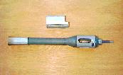
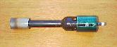
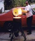
"Monster
Burner" and Melting Furnace
(This burner easily melts cast iron!)
Designed by Rupert Wenig, and submitted by Robert Grauman.
![]() This is a corker
of a burner that has been perfected by Rupert Wenig. It is an enlarged
version of my 'Reil Burner," but Rupert deserves all the credit for
this one since I never dreamed that the burner design I posted could
ever melt cast iron if scaled up. These guys up in Alberta enlarged the
burner and then used it in a melting furnace built to the Gingery
design. It easily melted 17 pounds of cast iron! The following images
show the burner, the furnace, and the results of their cast iron melt.
The burner also was used to melt aluminum, 2 kg in 10 minutes, and
brass, 6 kg in 19 minutes, ... very impressive times. The cast iron
took a little longer. The top link is the burner design drawing of the
"Monster Burner" by Rupert Wenig. I should add that the "Tee" pipe
coming off the side of the burner tube in the images is just a support
handle to mount it in the furnace. If you are considering this burner,
be sure to look at the Minimongo Burner
too before making a final decision as to what burner to use.
This is a corker
of a burner that has been perfected by Rupert Wenig. It is an enlarged
version of my 'Reil Burner," but Rupert deserves all the credit for
this one since I never dreamed that the burner design I posted could
ever melt cast iron if scaled up. These guys up in Alberta enlarged the
burner and then used it in a melting furnace built to the Gingery
design. It easily melted 17 pounds of cast iron! The following images
show the burner, the furnace, and the results of their cast iron melt.
The burner also was used to melt aluminum, 2 kg in 10 minutes, and
brass, 6 kg in 19 minutes, ... very impressive times. The cast iron
took a little longer. The top link is the burner design drawing of the
"Monster Burner" by Rupert Wenig. I should add that the "Tee" pipe
coming off the side of the burner tube in the images is just a support
handle to mount it in the furnace. If you are considering this burner,
be sure to look at the Minimongo Burner
too before making a final decision as to what burner to use.
Pattern
and Finished Cast Iron Casting
******************
Designed by Marshall Bienstock, photo by Bruce Freeman
Click Image for Enlargement
![]() The
"Bienstock Burner"
design above is a more sophisticated version of the basic propane
burner
that allows greater control of the forge atmosphere. It is more
complicated
to build, and also adds to the burner length considerably, which will
preclude
its use in compact situations. If you have the room, and want to spend
the
extra effort, this is an excellent burner.
The
"Bienstock Burner"
design above is a more sophisticated version of the basic propane
burner
that allows greater control of the forge atmosphere. It is more
complicated
to build, and also adds to the burner length considerably, which will
preclude
its use in compact situations. If you have the room, and want to spend
the
extra effort, this is an excellent burner.
*****************
Designed by Jay Hayes, photo by Ralph Kessler

Click Image for Parts Breakdown
Hot News...ITC-100 Needs Recoating Periodically
![]() I partially
rebuilt the chamber in my four burner forge today, Sunday, 3 Nov 02,
and had a very surprising result. The front half of the chamber was
showing all the use and abuse it had received over the last 5 years, so
today I decided to replace the front end firebricks, and recoat the
front half of the forge chamber, and the new firebricks, with ITC-100.
I recoated only the front half due to its constant use. When I finished
I allowed the ITC-100 to dry. I then lit the forge and allowed it to
run at idle, only a couple ounces of gas pressure, to cure the ITC-100.
I was surprised when I looked over after only a few minutes and saw the
mouth of the forge chamber glowing a bright orange, and at only idle
pressure. When I went over to look, there was a very definite line
where the new ITC-100 ended and the old was exposed. I brought the
pressure up to working pressure, 3 psi, and allowed it to continue
coming up to heat for about 5 minutes. At that point the entire front
half of the chamber was bright yellow-white, while the old ITC-100 on
the exposed back half, that was in front of the movable back wall, was
still dead black, no heat showing in the floor tile at all! There was
also a very definite line on the coated Kaowool chamber walls, where
the old and new ITC-100 met.
I partially
rebuilt the chamber in my four burner forge today, Sunday, 3 Nov 02,
and had a very surprising result. The front half of the chamber was
showing all the use and abuse it had received over the last 5 years, so
today I decided to replace the front end firebricks, and recoat the
front half of the forge chamber, and the new firebricks, with ITC-100.
I recoated only the front half due to its constant use. When I finished
I allowed the ITC-100 to dry. I then lit the forge and allowed it to
run at idle, only a couple ounces of gas pressure, to cure the ITC-100.
I was surprised when I looked over after only a few minutes and saw the
mouth of the forge chamber glowing a bright orange, and at only idle
pressure. When I went over to look, there was a very definite line
where the new ITC-100 ended and the old was exposed. I brought the
pressure up to working pressure, 3 psi, and allowed it to continue
coming up to heat for about 5 minutes. At that point the entire front
half of the chamber was bright yellow-white, while the old ITC-100 on
the exposed back half, that was in front of the movable back wall, was
still dead black, no heat showing in the floor tile at all! There was
also a very definite line on the coated Kaowool chamber walls, where
the old and new ITC-100 met.
![]() This was a big
shock to me. I didn't know that ITC-100 had such a definite life span.
At this writing I do not know what the useful life span of ITC-100 is,
but I hope to find out soon. Also, I do not know what signs indicate
that the ITC coating has lost its usefulness. The coating in my forge
had become very dark, even black on the floor of the forge. I only want
to alert the metalworking community that ITC-100 needs to be recoated
occasionally. How often still remains to be determined. I have been
having some problems with my forge welding, but chalked it up to sloppy
technique. Now I believe that I was not getting the temperature that I
was previously when forge welding was extremely easy. I will post more
info as soon as I learn more. The moral...recoat occasionally when your
ITC becomes greatly discolored. You may easily apply a little
test dab of ITC-100 in your forge and see if that spot becomes
significantly hotter than the rest of the surface. If it does, you
probably need to recoat.
This was a big
shock to me. I didn't know that ITC-100 had such a definite life span.
At this writing I do not know what the useful life span of ITC-100 is,
but I hope to find out soon. Also, I do not know what signs indicate
that the ITC coating has lost its usefulness. The coating in my forge
had become very dark, even black on the floor of the forge. I only want
to alert the metalworking community that ITC-100 needs to be recoated
occasionally. How often still remains to be determined. I have been
having some problems with my forge welding, but chalked it up to sloppy
technique. Now I believe that I was not getting the temperature that I
was previously when forge welding was extremely easy. I will post more
info as soon as I learn more. The moral...recoat occasionally when your
ITC becomes greatly discolored. You may easily apply a little
test dab of ITC-100 in your forge and see if that spot becomes
significantly hotter than the rest of the surface. If it does, you
probably need to recoat.
![]() Here is the
straight skinny, right from the source. This comes from Jock Dempsey, and
is self explainatory. I am quoting his e-mail with his permission. His
help is much appreciated.
Here is the
straight skinny, right from the source. This comes from Jock Dempsey, and
is self explainatory. I am quoting his e-mail with his permission. His
help is much appreciated.
Ron,
I have just spoken with Mr. Feriz Delkic, the owner of ITC, about your questions. He says that at forge temperatures there is absolutely no breakdown of the ITC-100. They have furnaces with oxidizing atmospheres in service for some 20 years without degradation of the coating.
In all probability the problem is soot, scale dust, and other debris that has attached to the surface. Mr. Delkic says with a light coating of debris the ITC-100 is still acting as an isolator and reflecting the infrared, but that the debris is filtering it. In a small forge or furnace this might effect the recovery time somewhat.
Predicting when this problem will occur would be impossible due to the many variables of individual forge usage. I would expect it has as much to do with how many times the forge is fired, and how long it is run each time.
Commercial usage forges may run non-stop for weeks, or at the least for a full 8 hours. In your shop and mine we may run the forge for an hour or two, shut it down, and run it for another hour later in the day. When I am casting with my little melting furnace, I run it for half an hour, shut down when I pour, and then fire back up for the next melt, maybe 5 or 10 times in a day. I would guess that if soot is the problem, then the number of cold restarts is a factor.
Forges are also exposed to scale and scale dust. Fine scale dust blows around in the forge, and the surface temperatures are high enough for it to melt and stick to those surfaces. As you know the ferric oxide can damage some refractories, such as the alumina in Kaowool. It does not damage the ITC-100, but it does cling to the surface. Again, this is not a failure of the ITC-100, but an operating condition particular to forges. Kilns and other types of furnaces each have their own pecularities.
I would say that recoating the forge with a thin wash at least once a year would be good practice. I have found that once a surface is coated that it takes very little to recoat it by brush application. Spraying may take more, as the consistancy must be just right to stick and not run.
![]() The
four burner
forge I built, using the
burners I discussed above,
has turned out to be an excellent forge in every respect. It was built
using
a custom rolled cylinder of 11 gage steel, lined with two 1" layers of
"Kaowool."
It is coated with
"ITC-100",
manufactured
by "International Technical Ceramics Corporation". The cylinder is 24"
long by 12" in diameter. I will not
provide any diagrams here as the images and narrative are enough to
allow
anyone with basic metal working skills to duplicate it, or a modified
version.
The
four burner
forge I built, using the
burners I discussed above,
has turned out to be an excellent forge in every respect. It was built
using
a custom rolled cylinder of 11 gage steel, lined with two 1" layers of
"Kaowool."
It is coated with
"ITC-100",
manufactured
by "International Technical Ceramics Corporation". The cylinder is 24"
long by 12" in diameter. I will not
provide any diagrams here as the images and narrative are enough to
allow
anyone with basic metal working skills to duplicate it, or a modified
version.
![]() I used 2" of "Kaowool"
liner, but perhaps 3" would be a good additional insurance if you are
at
higher elevations where forge performance might be marginal in
achieving
welding temperatures. I highly recommend "ITC-100" over the use of
"Satinite"
It is a superior IR reflector, reflecting back up to 98% of the heat
that
strikes it. This contributes to lower forge shell temperatures, higher
interior
temperatures, as well as fuel savings.
I used 2" of "Kaowool"
liner, but perhaps 3" would be a good additional insurance if you are
at
higher elevations where forge performance might be marginal in
achieving
welding temperatures. I highly recommend "ITC-100" over the use of
"Satinite"
It is a superior IR reflector, reflecting back up to 98% of the heat
that
strikes it. This contributes to lower forge shell temperatures, higher
interior
temperatures, as well as fuel savings.
![]() The floor of my forge
is rather special in design. I wanted to preserve as much insulation as
possible
so designed the floor to sit above an inch of kaowool at the extreme
edges,
and almost two inches in the bottom center. I used one half of a 12"x
24"x
1" high alumina kiln shelf. The 6" wide kiln shelf floor sits on six 1"
high
kiln shelf posts that are kept in place by 3/4"x 3/8" diameter rods
blind
welded into holes in the bottom of the shell. This prevents the weight
of
the floor plate from compressing the kaowool, and provides the
necessary
space to allow one full wrap of kaowool around the circumference of the
forge
shell. The second layer runs from one edge of the floor plate around to
the
other. I also added another strip of kaowool under the plate to fill up
the
gap in the center. Once all was in place, everything, including the
floor,
was coated with "ITC-100". When I eventually rework the interior of my
forge
I will make one modification. To protect the fragile Kaowool walls I
will
install two full length, by 2" wide, sections of kiln shelf on either
side
of the floor to act as bumper strips. They will be angled outward and
blend
in with the surface and curvature of the Kaowool liner. By doing this
the
forge will be much more resistant to mechanical damage in its interior.
The floor of my forge
is rather special in design. I wanted to preserve as much insulation as
possible
so designed the floor to sit above an inch of kaowool at the extreme
edges,
and almost two inches in the bottom center. I used one half of a 12"x
24"x
1" high alumina kiln shelf. The 6" wide kiln shelf floor sits on six 1"
high
kiln shelf posts that are kept in place by 3/4"x 3/8" diameter rods
blind
welded into holes in the bottom of the shell. This prevents the weight
of
the floor plate from compressing the kaowool, and provides the
necessary
space to allow one full wrap of kaowool around the circumference of the
forge
shell. The second layer runs from one edge of the floor plate around to
the
other. I also added another strip of kaowool under the plate to fill up
the
gap in the center. Once all was in place, everything, including the
floor,
was coated with "ITC-100". When I eventually rework the interior of my
forge
I will make one modification. To protect the fragile Kaowool walls I
will
install two full length, by 2" wide, sections of kiln shelf on either
side
of the floor to act as bumper strips. They will be angled outward and
blend
in with the surface and curvature of the Kaowool liner. By doing this
the
forge will be much more resistant to mechanical damage in its interior.
![]() I wanted to be able
to easily change the opening to the forge to suit the work at hand.
Although
my "brick wall" may not be as pretty as some other arrangements, it has
great
versatility in allowing any configuration needed to be instantly
arranged.
I constructed a "brick shelf" that is part of the forge for the bricks
to
sit on. All bricks are coated with ITC-100 also. The bricks are not
standard
fire bricks, but are ultra light weight high temperature kiln bricks.
They
run from $3.50-$4.00 US per brick, but their high thermal efficiency
justifies
the expense. Odd as it may seem, the less expensive bricks, $3.50, are
actually
better than the higher density and higher priced bricks because of
their
better insulation qualities.
I wanted to be able
to easily change the opening to the forge to suit the work at hand.
Although
my "brick wall" may not be as pretty as some other arrangements, it has
great
versatility in allowing any configuration needed to be instantly
arranged.
I constructed a "brick shelf" that is part of the forge for the bricks
to
sit on. All bricks are coated with ITC-100 also. The bricks are not
standard
fire bricks, but are ultra light weight high temperature kiln bricks.
They
run from $3.50-$4.00 US per brick, but their high thermal efficiency
justifies
the expense. Odd as it may seem, the less expensive bricks, $3.50, are
actually
better than the higher density and higher priced bricks because of
their
better insulation qualities.
![]() If you are new to forge
work, and especially to ceramic fiber insulation, you need to be aware
that
welding flux, such as borax, will eat through them as fast as water
through
cotton candy. That is one reason for the heavy kiln shelf floor plate.
I
also recommend you consider a piece of stainless plate, or sacrifical
piece
of kiln shelf, placed under your fluxed iron to protect the forge
floor,
since it will attack that as well.
If you are new to forge
work, and especially to ceramic fiber insulation, you need to be aware
that
welding flux, such as borax, will eat through them as fast as water
through
cotton candy. That is one reason for the heavy kiln shelf floor plate.
I
also recommend you consider a piece of stainless plate, or sacrifical
piece
of kiln shelf, placed under your fluxed iron to protect the forge
floor,
since it will attack that as well.
![]() The burner mounting
on my forge was done using threaded pipe sections that screw into pipe
couplings
that I sawed in half and welded to the shell. The pipe sections were
big
enough to allow free passage of the burner nozzle through into the
forge
chamber. The nozzle is held in position by two rings of three "set
screws",
in this case 1/4" diameter bolts. This allows me considerable
adjustability
on my burner positioning and aim. I don't believe in the commonly held
belief
that the burners should be mounted at a tangent to create a vortex in
the
forge. My experience indicates that it is not necessary, and may
in-fact
contribute to scaling. I have mine aimed to the side of the floor
plate,
but not on the wall of the chamber. I can adjust them to dead center if
desired,
or to a considerable angle to produce a vortex.
The burner mounting
on my forge was done using threaded pipe sections that screw into pipe
couplings
that I sawed in half and welded to the shell. The pipe sections were
big
enough to allow free passage of the burner nozzle through into the
forge
chamber. The nozzle is held in position by two rings of three "set
screws",
in this case 1/4" diameter bolts. This allows me considerable
adjustability
on my burner positioning and aim. I don't believe in the commonly held
belief
that the burners should be mounted at a tangent to create a vortex in
the
forge. My experience indicates that it is not necessary, and may
in-fact
contribute to scaling. I have mine aimed to the side of the floor
plate,
but not on the wall of the chamber. I can adjust them to dead center if
desired,
or to a considerable angle to produce a vortex.
![]() The penetration of the
burner nozzle goes only as far as the interior surface of the outside
layer
of kaowool. The interior layer of kaowool has a hole poked through it
with
a conical punch to continue the path to the interior of the forge. This
allows
the burner nozzles to be out of the extreme heat of the forge
preventing
any damage to them. The kaowool seals quite effectively around the
burner
nozzle preventing any blow-by from coming up between the burner tube
and
the mounting tube holding the burner.
The penetration of the
burner nozzle goes only as far as the interior surface of the outside
layer
of kaowool. The interior layer of kaowool has a hole poked through it
with
a conical punch to continue the path to the interior of the forge. This
allows
the burner nozzles to be out of the extreme heat of the forge
preventing
any damage to them. The kaowool seals quite effectively around the
burner
nozzle preventing any blow-by from coming up between the burner tube
and
the mounting tube holding the burner.
![]() There are two improvements
I have incorporated into this forge that are not normally found on gas
forges.
I use a movable back wall
inside the forge to reduce
the forge chamber dimensions to the minimum necessary for a particular
application. If the work is small, and I only need one burner, the wall
can
be slid all the way up to create a very small, but very efficient
chamber.
The movable back wall is made of a piece of "kaowool board" cut out to
allow
clearance around it for gas escape. It is also coated with "ITC-100" to
further
increase its efficiency as an IR reflector. This cuts down on heating
unused
space and increases fuel efficiency. Note: Please visit my
Forge Page for an
important update to this movable
back wall design. Look under "My Newest Forge Design", at the bottom
under
"Update".
There are two improvements
I have incorporated into this forge that are not normally found on gas
forges.
I use a movable back wall
inside the forge to reduce
the forge chamber dimensions to the minimum necessary for a particular
application. If the work is small, and I only need one burner, the wall
can
be slid all the way up to create a very small, but very efficient
chamber.
The movable back wall is made of a piece of "kaowool board" cut out to
allow
clearance around it for gas escape. It is also coated with "ITC-100" to
further
increase its efficiency as an IR reflector. This cuts down on heating
unused
space and increases fuel efficiency. Note: Please visit my
Forge Page for an
important update to this movable
back wall design. Look under "My Newest Forge Design", at the bottom
under
"Update".
![]() The second big improvement
I incorporated into my forge concerns the plumbing for the four
burners.
I used individual ball valves for each burner. This allows me to use
only
the number of burners necessary for the work at hand. The second
modification
is the use of two valves on the gas inlet line. They are configured in
a
parallel arrangement
with one of them a normal
ball valve (on/off), and the other a needle valve to allow precise
control
of a small gas flow to the burner. With this arrangement I can adjust
the
input gas pressure to whatever working pressure I need using the
regulator,
and then with the "on/off? valve to the "off" position, adjust the
needle
valve for a minimum burn level, an idle flow rate.
The second big improvement
I incorporated into my forge concerns the plumbing for the four
burners.
I used individual ball valves for each burner. This allows me to use
only
the number of burners necessary for the work at hand. The second
modification
is the use of two valves on the gas inlet line. They are configured in
a
parallel arrangement
with one of them a normal
ball valve (on/off), and the other a needle valve to allow precise
control
of a small gas flow to the burner. With this arrangement I can adjust
the
input gas pressure to whatever working pressure I need using the
regulator,
and then with the "on/off? valve to the "off" position, adjust the
needle
valve for a minimum burn level, an idle flow rate.
![]() With this arrangement
I can instantly shut the forge down to a minimum burn rate while I am
at
the anvil, and when I return to the forge can instantly return to my
full
working pressure with just a flip of the "on/off" valve. Since I
sometimes
spend extended periods at the anvil this results in considerable gas
savings.
To shut off the forge I use the individual burner valve(s). It took me
a
day to get used to flipping the valve on and off each time I went to
the
anvil, but quickly became an automatic response for me. I highly
recommend
this modification. (For more complete information on the idle/full
valve
arrangement, including images, consult the Four
Burner Forge Design description on my Forge and Foundry
Page.)
With this arrangement
I can instantly shut the forge down to a minimum burn rate while I am
at
the anvil, and when I return to the forge can instantly return to my
full
working pressure with just a flip of the "on/off" valve. Since I
sometimes
spend extended periods at the anvil this results in considerable gas
savings.
To shut off the forge I use the individual burner valve(s). It took me
a
day to get used to flipping the valve on and off each time I went to
the
anvil, but quickly became an automatic response for me. I highly
recommend
this modification. (For more complete information on the idle/full
valve
arrangement, including images, consult the Four
Burner Forge Design description on my Forge and Foundry
Page.)
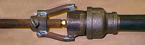
![]() I used all brass valves
and plumbing on my forge, but iron will do as well, and at much lower
cost.
I also have a quick disconnect on the forge so that I can easily
disconnect
the propane tank. This is a very useful addition.
I used all brass valves
and plumbing on my forge, but iron will do as well, and at much lower
cost.
I also have a quick disconnect on the forge so that I can easily
disconnect
the propane tank. This is a very useful addition.
![]() I will conclude with
a few comments on the operation of my forge. Any burners that are being
used
will remain very cool to the touch while in use. They will heat up once
the
forge is shut down however, so watch what you touch. The burners that
are
not being used provide an open chimney to the forge, and the ultra hot
gasses
will pass right out through them heating them to dangerous
temperatures.
To prevent this I simply stuff a small wad of paper towel into the
throat
of each unused burner. When I wish to add a burner, even when the forge
is
running, I simply use a pair of needle nose pliers to pull the plug
out,
and then switch on the gas valve. The paper will not burn while in the
burner
tube.
I will conclude with
a few comments on the operation of my forge. Any burners that are being
used
will remain very cool to the touch while in use. They will heat up once
the
forge is shut down however, so watch what you touch. The burners that
are
not being used provide an open chimney to the forge, and the ultra hot
gasses
will pass right out through them heating them to dangerous
temperatures.
To prevent this I simply stuff a small wad of paper towel into the
throat
of each unused burner. When I wish to add a burner, even when the forge
is
running, I simply use a pair of needle nose pliers to pull the plug
out,
and then switch on the gas valve. The paper will not burn while in the
burner
tube.
![]() Some smiths like the
thermal mass of a poured in place refractory lining in their forges.
There
are both advantages and disadvantages in such linings. In my case, I
like
to have my forge cool down as quickly as possible when I shut down
since
I use it outside and
need to cover it. Poured in
place linings take a very long time to cool. The poured in place
lining,
let's call it "rigid lining", is far more forgiving of the abuse that
careless
handling of the iron can cause. On the other hand it is far less
thermally
efficient as an insulator. This may mean the difference in achieving,
or
not achieving, welding temperatures at higher elevations, and in some
case
lower ones as well. If you will want to move your forge, the ceramic
wool
liner will certainly be superior for your needs.
Some smiths like the
thermal mass of a poured in place refractory lining in their forges.
There
are both advantages and disadvantages in such linings. In my case, I
like
to have my forge cool down as quickly as possible when I shut down
since
I use it outside and
need to cover it. Poured in
place linings take a very long time to cool. The poured in place
lining,
let's call it "rigid lining", is far more forgiving of the abuse that
careless
handling of the iron can cause. On the other hand it is far less
thermally
efficient as an insulator. This may mean the difference in achieving,
or
not achieving, welding temperatures at higher elevations, and in some
case
lower ones as well. If you will want to move your forge, the ceramic
wool
liner will certainly be superior for your needs.
![]() If you are not familiar
with the products I have discussed here, and their sources, try calling
your
local pottery supply store. They cary kilns and supplies such as
"Kaowool"
and "ITC-100", as well as "Satinite". If they don't have them on hand
they
can order them for you. When you are there look around at the various
types
of refractory products they cary. You will be able to get your kiln
shelf
floor plate and support posts there as well. You may have to look
around
however to find a place that will sell small quantities in some cases.
If
you are unable to locate ITC-100, it is made by "International
Technical
Ceramics" which you should be able to locate on the internet, and
contact
to find a local source.
If you are not familiar
with the products I have discussed here, and their sources, try calling
your
local pottery supply store. They cary kilns and supplies such as
"Kaowool"
and "ITC-100", as well as "Satinite". If they don't have them on hand
they
can order them for you. When you are there look around at the various
types
of refractory products they cary. You will be able to get your kiln
shelf
floor plate and support posts there as well. You may have to look
around
however to find a place that will sell small quantities in some cases.
If
you are unable to locate ITC-100, it is made by "International
Technical
Ceramics" which you should be able to locate on the internet, and
contact
to find a local source.
See Also the
Construction of My Freon Tank
Mini-forge
Some Additional Gas Forge Designs
Forge #1
Submitted by: Matthew Wills, design by Matt and others
Forge #2
Submitted by: Richard Sevigny Richard's tiny forge was inspired by Ed Halligan's
design as posted by Donnie Fulwood!
Forge #3
Submitted by: Harry Foster A very cute tiny forge.
Forge #4
Submitted by: Larry Zoeller
This is a micro forge that uses a propane torch for heat. Cute forge!
Forge #5
"Sandia Recuperative Forge Design"
![]() Note
on an alternative to the Sandia Forge, the Clamshell Forge design:
The Sandia Forge
is a very sophisticated forge design requiring an extraordinary amount
of
labor to build. It is of particular value for wide flat forgings like
scrolls.
We are building some interesting forges that have a large flat floor,
18"
x 24" or larger, and a flat top lid that is attached to a vertical lift
system.
The lid lift system can be as simple as a camper-jack, or as complex as
a camper jack combined with a foot treadle for raising, and a dash-pot
for lowering the lid. You can crank up the lid
and stack a wall of fire bricks around the edge of the floor in
whatever
arrangement and height you require, then lower the lid to close it in.
You
can also lay a refractory rope on top of the bricks to get a tight
seal.
The burners can be top or bottom mounted, and the top can also have an
additional
treadle lift for instant opening. This allows total versatility to set
up
the forge for whatever the task at hand requires. This offers far
greater versatility than the Sandia forge, and the work is less than
that required to build the Sandia forge. Using high quality burners
like
the Rex series, an idle/full valve arrangement, and ITC-100 interior
coating, the Clam-shell will almost certainly match, and probably
exceed the Sandia in both
operating temperature and fuel efficiency. I say "probably," because
there
are so many possible variations of this forge, and different insulating
options,
that you would have to compare specific forges for a definite answer. I
have a Zip file
of information about the Clam-shell that you may download
if interested. Ralph Sproul provided me with some of the images in the
Zip file, as well as a copy of his very well done Clam-shell forge
plans. I highly recommend you contact Ralph
if you are interested in this forge design. Nahum Hersom provided me
with some of the information too. Also, talk with me by phone because
there are
some very useful additions and modifications I can recommend to you.
The Clamshell is as close to being a "do-all" forge design as exists.
Note
on an alternative to the Sandia Forge, the Clamshell Forge design:
The Sandia Forge
is a very sophisticated forge design requiring an extraordinary amount
of
labor to build. It is of particular value for wide flat forgings like
scrolls.
We are building some interesting forges that have a large flat floor,
18"
x 24" or larger, and a flat top lid that is attached to a vertical lift
system.
The lid lift system can be as simple as a camper-jack, or as complex as
a camper jack combined with a foot treadle for raising, and a dash-pot
for lowering the lid. You can crank up the lid
and stack a wall of fire bricks around the edge of the floor in
whatever
arrangement and height you require, then lower the lid to close it in.
You
can also lay a refractory rope on top of the bricks to get a tight
seal.
The burners can be top or bottom mounted, and the top can also have an
additional
treadle lift for instant opening. This allows total versatility to set
up
the forge for whatever the task at hand requires. This offers far
greater versatility than the Sandia forge, and the work is less than
that required to build the Sandia forge. Using high quality burners
like
the Rex series, an idle/full valve arrangement, and ITC-100 interior
coating, the Clam-shell will almost certainly match, and probably
exceed the Sandia in both
operating temperature and fuel efficiency. I say "probably," because
there
are so many possible variations of this forge, and different insulating
options,
that you would have to compare specific forges for a definite answer. I
have a Zip file
of information about the Clam-shell that you may download
if interested. Ralph Sproul provided me with some of the images in the
Zip file, as well as a copy of his very well done Clam-shell forge
plans. I highly recommend you contact Ralph
if you are interested in this forge design. Nahum Hersom provided me
with some of the information too. Also, talk with me by phone because
there are
some very useful additions and modifications I can recommend to you.
The Clamshell is as close to being a "do-all" forge design as exists.
![]() Submitted
by:
Chuck Kishaba
This very fine forge is
a recuperative propane forge built from the "Sandia National Labratory"
plans
which are available from ABANA.
The images show various views of the finished forge, along with two
images
of it heating some 1" diameter bars. This is such a fine piece of work
that
I am going to quote Chuck's entire e-mail explaining the following
images.
His excellent description follows. Much thanks Chuck.
Submitted
by:
Chuck Kishaba
This very fine forge is
a recuperative propane forge built from the "Sandia National Labratory"
plans
which are available from ABANA.
The images show various views of the finished forge, along with two
images
of it heating some 1" diameter bars. This is such a fine piece of work
that
I am going to quote Chuck's entire e-mail explaining the following
images.
His excellent description follows. Much thanks Chuck.
Chuck' Description;
Well, here they are. Let me give
you some info on each JPEG
photo.
1) forge5.jpg
is a 3/4 front view of the
forge
2) forge6.jpg is
a 3/4 rear view of the
forge
3) forge3.jpg is
a front shot with the door
open
4) forge11.jpg
is a close up shot of the heated
bars
5) forge8.jpg is
a shot of a cold forge with the
cold samples prior to light up
6) forge9.jpg is
a shot of the bars being
heated
7) forge10.jpg
is a shot of the bars after 8 minutes
from a cold start
My story:
I needed an economical means to flatten the ends of 1"
diameter solid
round
bars. I looked into induction heaters (incredibly expensive)
and
commercial
propane forges. I'm not a blacksmith and needed something that
I could
light
up, do my work, and shut down. I liked the efficient design of
the
Sandia
forge and decided to buy the plans from ABANA. The forge was
not easy
to make.
It helps to have sheet metal skills and a lot of patience to
fit the
ceramic
insulation board. It took me about 3 months working in my
spare
time.
Description:
Air enters 2 flattened stainless steel preheater tubes from
the rear of
the
forge. This air then mixes with the propane, and the air/fuel
mixture
goes into
a ventouri that necks down to the burner tubes. The exhaust
gases exit
the rear
vertical chimney which pass around the 2 flattened stainless
steel
preheater
tubes. This feature preheats the intake air to 1000F. The
preheated
air
increases the velocity of the mixture and this results in a
hotter
forge,
and a 25% savings in fuel. The white insulation
covering the burner
tubes is
1" kaowool wrapped in stainless steel wire screen. The main
insulation
is 1"
thick 2600 ceramic insulation board. I obtained it from
Thermal
Ceramics.
I paid $26.00 per square foot for the board.
Changes:
The biggest change I made from the ABANA plans was the door.
The
original
plans call for a door without the oval opening, only a notch
in one corner.
My
door does lose some efficiency, but as you can see from the
photos, works
quite
well for my purpose. The stand is also different from the
ABANA plans
but has
no effect on performance.
Performance:
Photo (forge8.jpg)
is a shot of a cold forge with
five 1" solid round 1018 bars
ready to be heated.
Photo (forge9.jpg)
is a shot of the forge 30 seconds
after startup with the five
bars inserted into the door.
Photo (forge10.jpg)
shows the five bars after
8 minutes. This is all from a cold
start with the bars inserted immediately after startup!
I've ran the forge for about
1-1/2 hours from a 30 lb propane
tank with no
freeze-up. I usually run about 5-7 psi of pressure.
Conclusion:
I am extremely pleased with the performance of this forge. It
works
better
than I imagined and was worth the expense of the ceramic board
and
difficulty
of construction. I would like to thank Robb Gunter, Karl
Schuler, and
Ronald
Ward of Sandia National Labs for their excellent design.
ABANA is on the web at:
abana.org. To order the plans, go the the site
and click on "ordering" On the ordering page you will find a
listing
for
"recuperative forge plans".
Good Luck!
Chuck Kishaba
Los Angeles CA
Forge #6
By: Steve Smith
![]() This is
a copy
of a newsletter article that Steve
Smith
wrote, and has very generously allowed me to post to my site. It
describes
the construction of his large gas forge in detail. If you are
considering
building a forge you may want to read this document to get another
description
and viewpoint of building a large gas forge. Click the title to visit
this
page. Thank you.
This is
a copy
of a newsletter article that Steve
Smith
wrote, and has very generously allowed me to post to my site. It
describes
the construction of his large gas forge in detail. If you are
considering
building a forge you may want to read this document to get another
description
and viewpoint of building a large gas forge. Click the title to visit
this
page. Thank you.
Links To Forge
& Burner Designs,
or Images
Don
Fogg, Bladesmith-Gas
Forge and Burner
David W. Wilson's Forge Design Page (Two designs)
"Tales of a New Blacksmith" by: Marc Godbout...must reading for the new smith.
![]() There
is now a counterpart to my gas forge site that is dedicated to coal
forges, Forge
and Fire. Matthew
Rutz has done a superb job of posting a large body of coal
forge information to his site. Be sure to explore all of his site, it
is extensive and rich in content.
There
is now a counterpart to my gas forge site that is dedicated to coal
forges, Forge
and Fire. Matthew
Rutz has done a superb job of posting a large body of coal
forge information to his site. Be sure to explore all of his site, it
is extensive and rich in content.
![]() I
have already covered
the construction of my big coal forge in some detail on my
"Forge and Foundry Page",
so I will refer you
to that location. Forges for coal can be very simple, no more than an
old
barbecue fixed up with an air supply coming in from the bottom with a
clay
lining in the pan, to the very complex, and difficult to build, forge
you
will see on my page. I will post pictures of coal forges from other
smiths
as I come across them and feel they are particularly useful or clever
in
some way.
I
have already covered
the construction of my big coal forge in some detail on my
"Forge and Foundry Page",
so I will refer you
to that location. Forges for coal can be very simple, no more than an
old
barbecue fixed up with an air supply coming in from the bottom with a
clay
lining in the pan, to the very complex, and difficult to build, forge
you
will see on my page. I will post pictures of coal forges from other
smiths
as I come across them and feel they are particularly useful or clever
in
some way.
![]() BRAKE DRUM FORGE:
You can quite easily build a very serviceable
forge from a big cast
iron truck brake drum. The hole is already provided in the bottom to
bolt
in your air grate, a piece of 1/4" steel plate with holes drilled in
it.
You only need to attach a plumbing "Tee" on the bottom to provide an
inlet
for your air, and also to be your ash dump. Put some legs on it, and a
blower
of some kind, and your in business. These forges do not even need to be
lined
with anything, and most of them have a fairly deep bowl giving you a
good
deep fire. Their only down side is that you will have a difficult time
getting
long stock into them for heats in the center area of the stock. A
friend
of mine, who is a very good smith, uses one of these forges and is able
to
make remarkable things with it. He cut out two slots, one on either
side,
and installed doors to allow long items to be heated. He also has a
chimney
installed to prevent breathing too much of the smoke.....a great
idea.
I hope to have a picture of his forge here soon.
Robert Bordeaux
has provided a
unique design in which he
uses the brake drum as
the bottom fire-pot, and expands upward into a blower housing, creating
a
much larger pan. The forge is lined with a 1/2" thick layer of furnace
cement.
Robert deserves lots of thanks also for his contribution of the
"Bordeaux
modification" to the burner design I have posted above. It is a superb
modification.
BRAKE DRUM FORGE:
You can quite easily build a very serviceable
forge from a big cast
iron truck brake drum. The hole is already provided in the bottom to
bolt
in your air grate, a piece of 1/4" steel plate with holes drilled in
it.
You only need to attach a plumbing "Tee" on the bottom to provide an
inlet
for your air, and also to be your ash dump. Put some legs on it, and a
blower
of some kind, and your in business. These forges do not even need to be
lined
with anything, and most of them have a fairly deep bowl giving you a
good
deep fire. Their only down side is that you will have a difficult time
getting
long stock into them for heats in the center area of the stock. A
friend
of mine, who is a very good smith, uses one of these forges and is able
to
make remarkable things with it. He cut out two slots, one on either
side,
and installed doors to allow long items to be heated. He also has a
chimney
installed to prevent breathing too much of the smoke.....a great
idea.
I hope to have a picture of his forge here soon.
Robert Bordeaux
has provided a
unique design in which he
uses the brake drum as
the bottom fire-pot, and expands upward into a blower housing, creating
a
much larger pan. The forge is lined with a 1/2" thick layer of furnace
cement.
Robert deserves lots of thanks also for his contribution of the
"Bordeaux
modification" to the burner design I have posted above. It is a superb
modification.
![]() NOTE:
Coal smoke will do bad things to
your lungs and body
over time, so a chimney is very important on any coal forge, indoors or
outdoors.
NOTE:
Coal smoke will do bad things to
your lungs and body
over time, so a chimney is very important on any coal forge, indoors or
outdoors.
![]() FIRE-POT
DESIGN: Bill
Franchini has provided the following
home built clinker breaker
fire-pot design. It is straight forward, except that the drawing shows
the
use of a square section tuyere, instead of a 4" diameter pipe. He built
it
this way simply because he didn't have 4" pipe available. It should be
easier
to construct using the pipe.If I were building this fire-pot I would
make
the fire grate out of two separate pieces. One part would be a grill
fabricated
out of the materials shown in the drawing, with "fingers" for the grill
elements,
and the portion that is actually attached to the rotating handle would
be
another set of "fingers" that would pass between and through the grate
fingers
as it was rotated, thus reducing the loss of coal Bill mentions in his
instructions document.
FIRE-POT
DESIGN: Bill
Franchini has provided the following
home built clinker breaker
fire-pot design. It is straight forward, except that the drawing shows
the
use of a square section tuyere, instead of a 4" diameter pipe. He built
it
this way simply because he didn't have 4" pipe available. It should be
easier
to construct using the pipe.If I were building this fire-pot I would
make
the fire grate out of two separate pieces. One part would be a grill
fabricated
out of the materials shown in the drawing, with "fingers" for the grill
elements,
and the portion that is actually attached to the rotating handle would
be
another set of "fingers" that would pass between and through the grate
fingers
as it was rotated, thus reducing the loss of coal Bill mentions in his
instructions document.
Additional Coal Forge Designs and Misc
Brake Drum Forge at Anvilfire.com
Paul Stevens' Brake Drum Forge
![]() Thanks to the
efforts of Paul
Stevens there is now a glossary
of blacksmithing terms available for new folks to consult if
needed. Check it out. :-)
Thanks to the
efforts of Paul
Stevens there is now a glossary
of blacksmithing terms available for new folks to consult if
needed. Check it out. :-)
Me in my Utilikilt - superior wear for blacksmithing -or- how to get toasty knees. :-)
My Younger Daughter and
Me at the Hagerman National Fish Hatchery
The Full Site Map - Lists All Pages on This Site

23 Nov 07
©Golden Age Forge

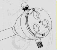
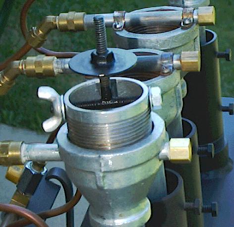
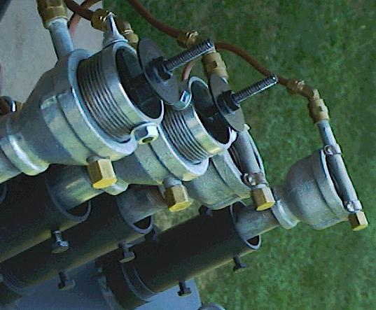
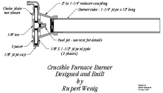
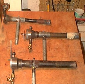
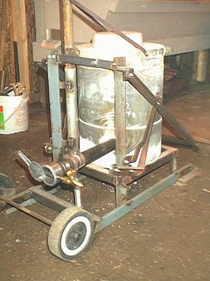
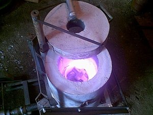
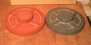
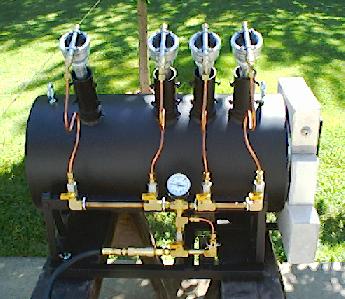
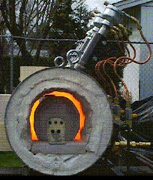
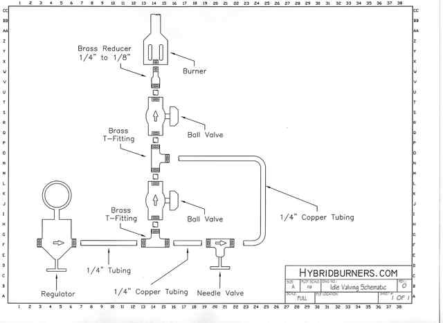
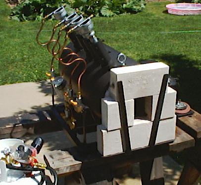
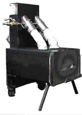
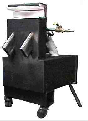
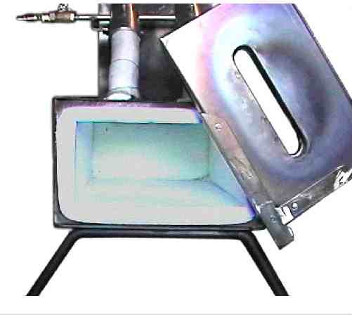
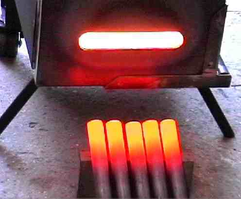
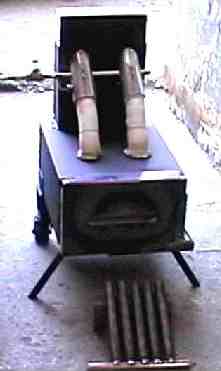
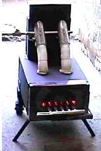
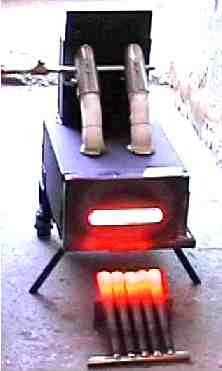
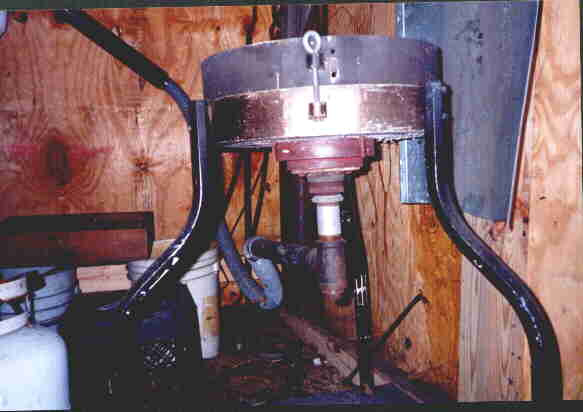
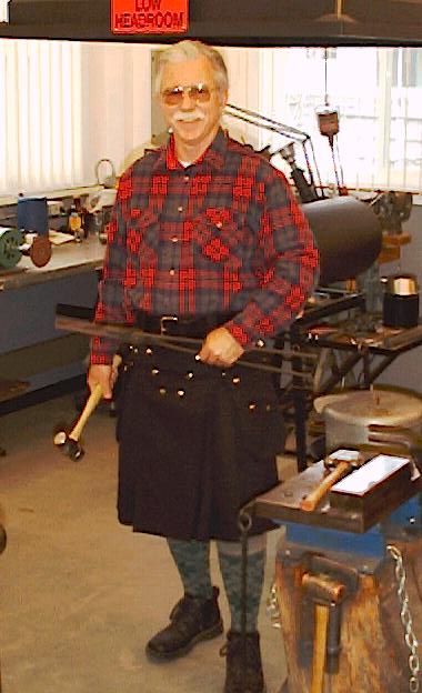